| IEC Fusion Reactor Mark 3 Vacuum Hub |
 |
 |
 |
 |
 |
 |
 |
| Overview: The Mark 3 reactor vacuum hub was constructed out of the Mark 2 reactor
concept prototype vacuum hub. |
|
|
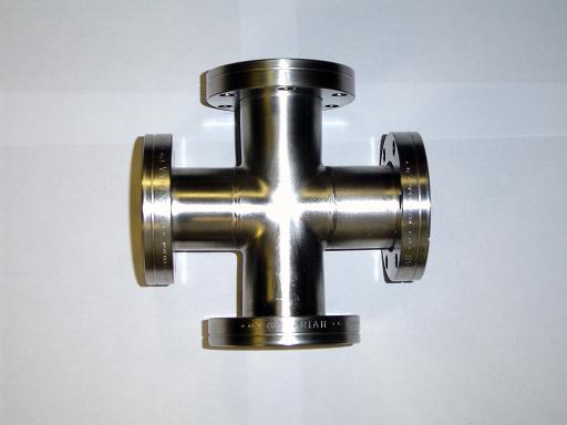
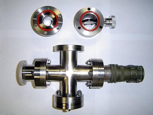
Cross (2005): 2.75" CF cross, 2 rotatable flanges. Cross will serve as the reactor vacuum hub, providing vacuum connection, an electrical feed through, and one instrumentation well. |
|
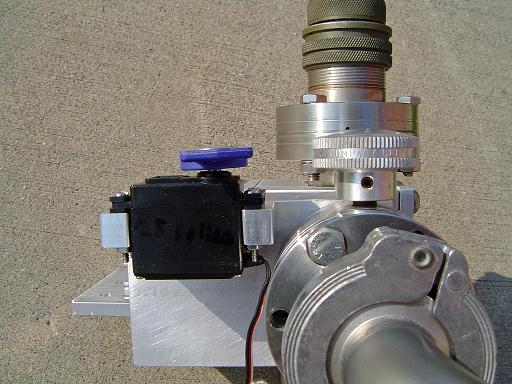
Throttling Valve (2005): Throttling butterfly valve is added to vary pumping rate. A NW-25 to 2.75 conflat adaptor attaches to the top of the throttling valve to adapt the vacuum hub to the vacuum system. |
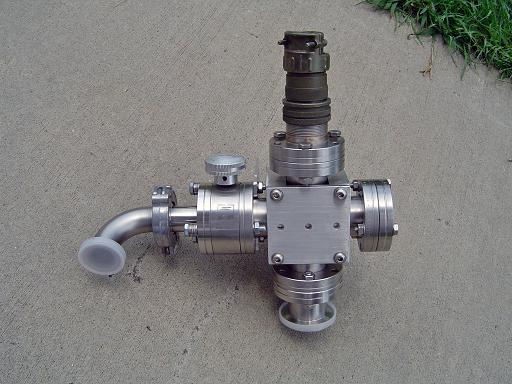 |
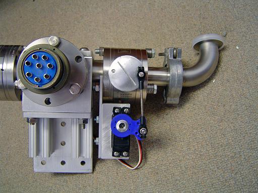
Vacuum hub (2005-2006): Assembled vacuum hub.
|
 |
|
 |
|
 |
|
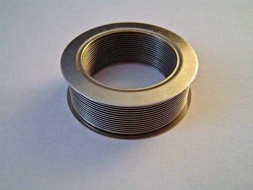 |
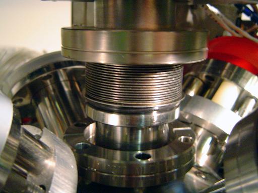
Bellows (01/20/2008) Thin wall bellows will connect core to vacuum hub. Bellows will seal to conflat flanges with viton o-rings. |
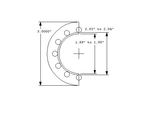 |
Bellows clamp flange (01/20/2008) Bellows mount is machined out of G10-FR4 fiberglass and is electrically insulating, allowing the core to be electrically insulated from the vacuum system and frame. Mounting lip is 0.1" deep.
|
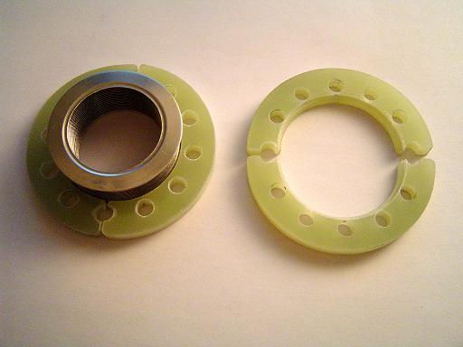 |
Bellows clamp flange (01/20/2008) Clamp flange on bellows and spare pair showing mounting groove. |
 |
Bellows o-ring (01/20/2008) O-ring seals bellows to core and insulates vacuum hub from core allowing current monitoring and biasing on each hemisphere. |
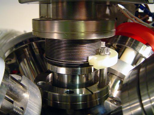 |
Bellows clamp (01/20/2008) Groove in clamp compresses the bellows' lip against the o-ring. |
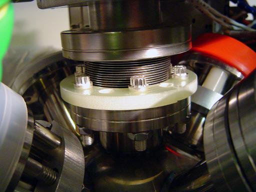 |
Bellows clamp (01/20/2008) Both clamps tighten down clamping bellows to core conflat. The o-ring on the vacuum hub is compressed by the springiness of the bellows until it is under vacuum, where the atmospheric pressure creates a hard seal. |
Bellows spacer (2/06/2008) Spacers are inserted between the flanges to prevent the bellows from collapsing under vacuum. |
|
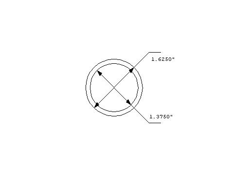 |
O-ring retaining ring (2/19/2008) Retaining ring is inserted into top o-ring to prevent it from slipping while under vacuum. |
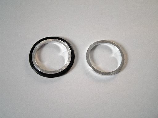 |
O-ring retaining ring (2/19/2008) Retaining ring is inserted into top o-ring to prevent it from slipping while under vacuum. |
|
|
| Useful links: http://www.fusor.net/ Open Source Fusion Research Consortium. |
|
By attempting to reproduce any experiments or devices listed on this domain in part or in whole, you agree to hold me harmless against any lawsuit or liability. Copyright © 1998 - 2005 by Andrew Seltzman. All rights reserved. |
|
| Contact me at: admin@rtftechnologies.org | |