| Mark 3 ECRF Ion Injector |
 |
 |
 |
 |
 |
 |
 |
| Overview: The ECRF injector will operate in a grounded extractor cone, asymmetric mirror configuration. In order to impart the full potential of the injector, the extractor cone will be grounded, while the antenna in the ionization cup is biased at +15kV in order to impart the greatest energy to a deuterium ion traveling to the negatively biased inner grid.
|
|
Injector Design Power point (Spring 2007) Power point for physics senior seminar 2
|
|
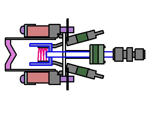 |
Injector CAD (3/17/2007)
|
 |
Electrostatic extractor field (5/28/2007) Electrostatic field for extracting ionized deuterium from injector. Modeled in Comsol 3.3. |
-Zsl-Zfd.jpg) |
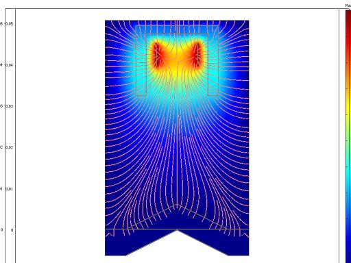
Magnetostatic axial field (5/28/2007) Magnetic field to generate ECRF resonance in the injector plasma. Slice across axis at antenna coil position. |
-Ysl-Zstream-overlay.jpg) |
Magnetostatic axial field (5/28/2007) Magnetic field to generate ECRF resonance in the injector plasma. Slice across magnets with field streamlines. |
 |
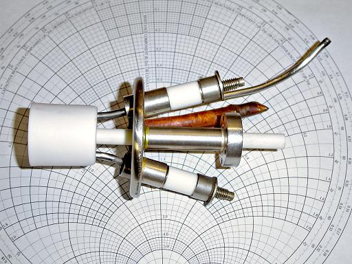
Injector Feed through (2/3/2006) Ion injector feed through will provide a balanced RF signal between both electrodes, as well as a 5kV bias. |
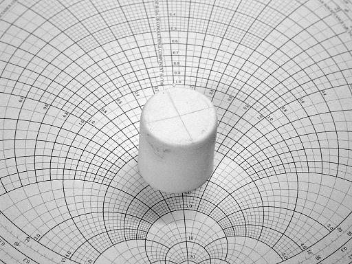 |
Ionization Cup (2/3/2006) High alumina crucible will be used as an ionization cup. |
 |
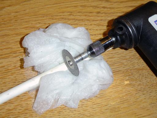
Dremel (2/3/2006) Dremel equipped with a right angle adaptor and diamond powder cutting burr. |
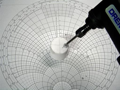 |
Drilling Electrode Holes (2/3/2006) Electrode holes are drilled into ionization cup. |
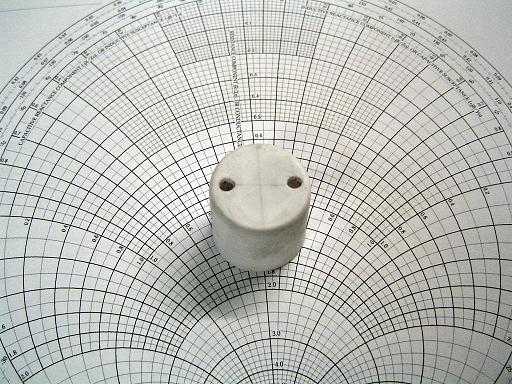 |
Electrode Holes (2/3/2006) |
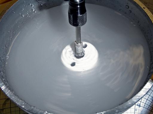 |
Gas Feed Through (2/3/2006) Gas feed through is bored into ionization cup. |
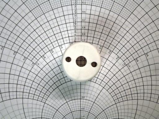 |
Complete Cup (2/3/2006) Ionization cup with gas and electrode holes drilled. |
 |
Gas Feed Through (2/3/2006) High alumina rod with 1/4" OD and 1/8" ID is cut to 3.5" lengths. |
 |
Ionization Cup In Place (2/3/2006) |
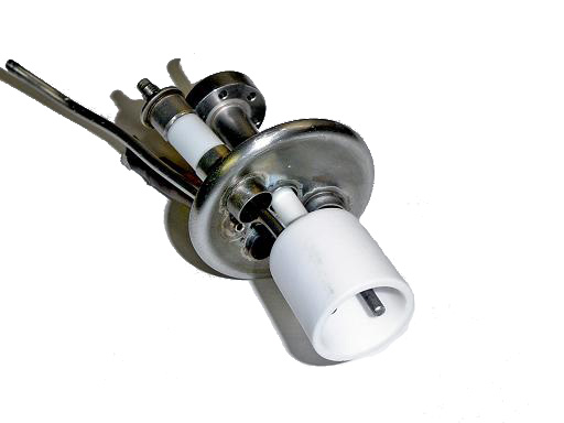 |
Ionization Cup In Place (2/3/2006) |
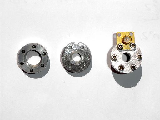 |
RF / O-ring Mount (4/3/2006) RF mount will clamp o-ring against feed through flange sealing against the ceramic deuterium feed through and provide a mounting location for the SMA connector. L to R: Original flange, machined RF mount, RF mount with SMA connector bolted on.
|
 |
O-ring (4/12/2006) O-ring fits around ceramic gas feed through and seals to mating flange. |
 |
O-ring Compressed (4/12/2006) RF mounting flange compresses o-ring against the ceramic tube and the body flange. |
 |
Gas Connector (4/12/2006) Swagelok gas connector attaches to ceramic tube via teflon ferrules. |
 |
RF and Gas Connections (4/12/2006)
|
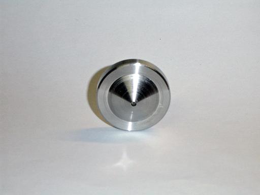 |
Extractor Cone (4/14/2006) Fabricated out of 304L stainless. |
 |
ECRF injector magnet mount (12/21/2006) |
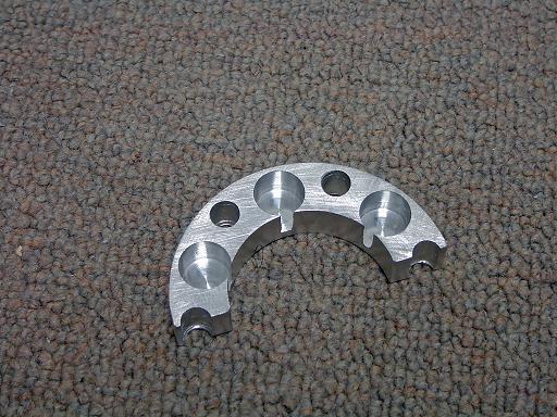 |
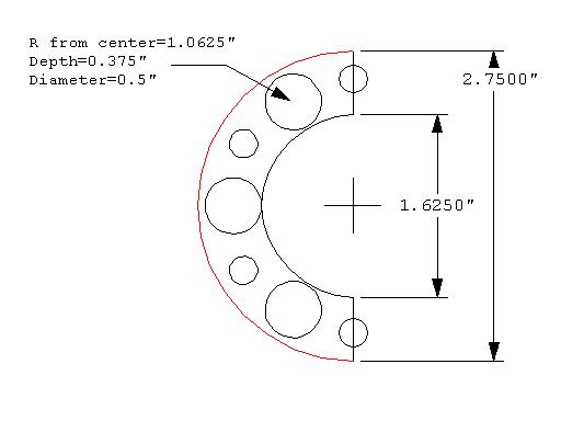
ECRF injector magnet mount (12/21/2006) Milled out of 1/2" aluminum, each will mount three 0.5" diameter by 1" length rare earth magnets. New magnets will allow operation at 900MHz ECRF excitation. |
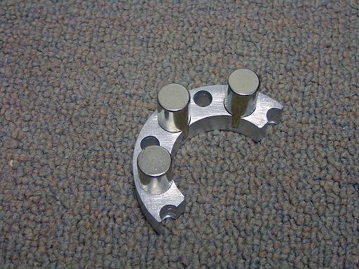 |
ECRF injector magnet mount (12/21/2006) Magnets mounted in mounting assembly. |
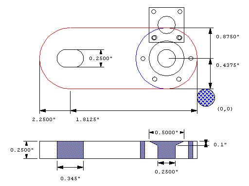 |
RF / O-ring /HV Mount (3/17/2007) G10-FR4 fiberglass mount replaces previous aluminum mount. Fiberglass mount contains a slot to attach the HV line through a banana jack. |
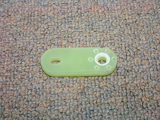 |
RF / O-ring /HV Mount (3/17/2007) Angled countersink compresses 1/4" ID, 1/8" thick o-ring onto high alumina gas feed through and mating flange. |
 |
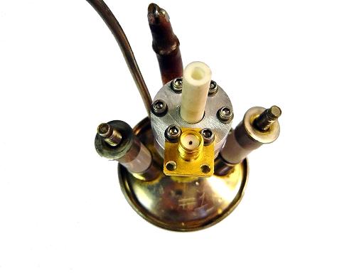
ECRF injector (3/17/2007) Magnet mounts attached to a 2.75" conflat half nipple. |
 |
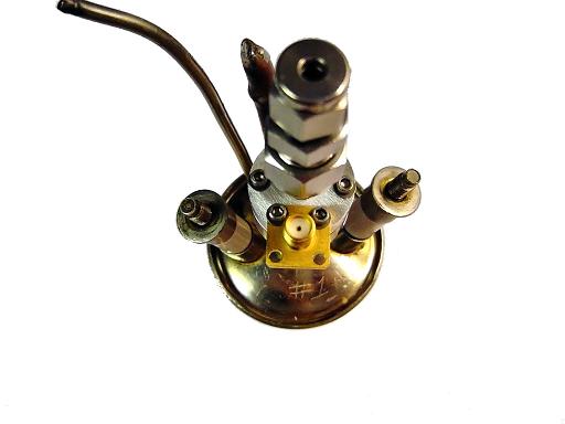
ECRF injector (3/17/2007)
|
 |
ECRF injector (3/17/2007)
|
 |
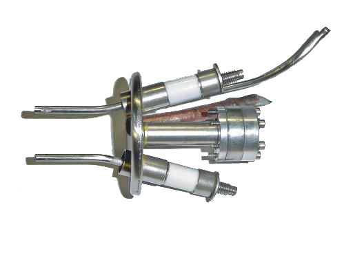
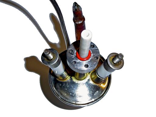
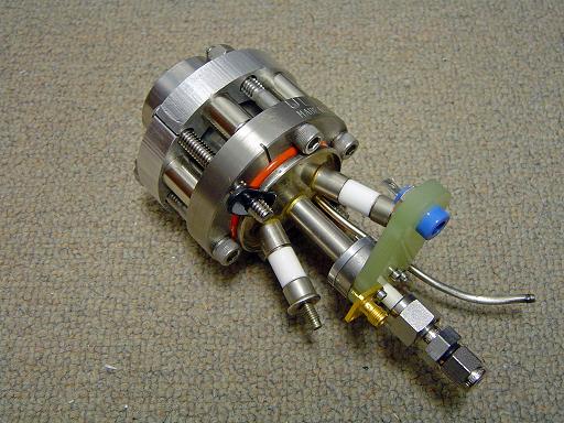
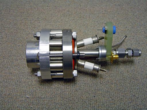
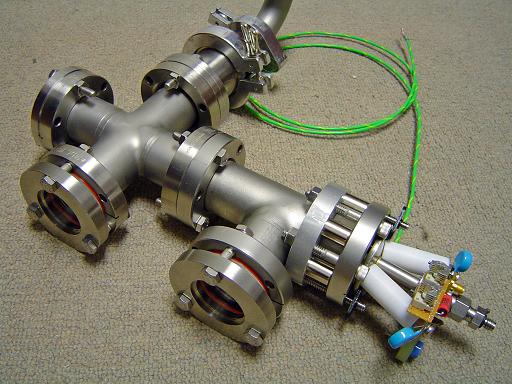
Feed through covers (5/25/2007) Electrical feed throughs are shielded with a teflon cylinder to allow operation up to 15kV without the insulators arcing over to the gas feed through. Injector is shown with RF matching network and HV decoupling capacitors attached. |
 |
Molybdenum wire (5/25/2007) 0.03" diameter molybdenum wire is used to fabricate the antenna coil. Molybdenum was chosen due to its higher melting temperature, better conductivity and lower sputtering coefficient when compared to stainless steel. |
 |
Antenna coil (5/25/2007) Molybdenum antenna coil is approximately 1cm in diameter, 0.8cm high and has 5.5 turns. |
 |
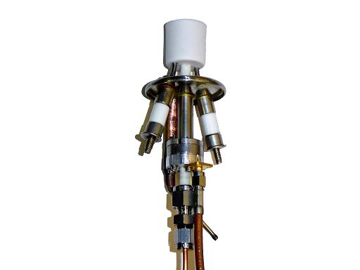
Injector test bed (5/25/2007) Injector is coupled to test bed for testing of antenna system. |
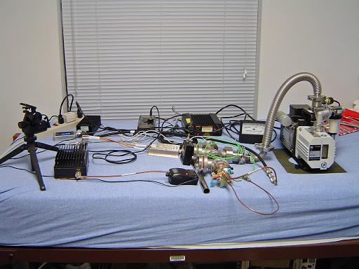 |
Injector ICP test setup (5/25/2007) RF ionization is preliminarily tested as an inductively coupled plasma at 150MHz instead of at the ECRF resonance frequency of 900MHz since the 900MHz drive system is not yet complete. |
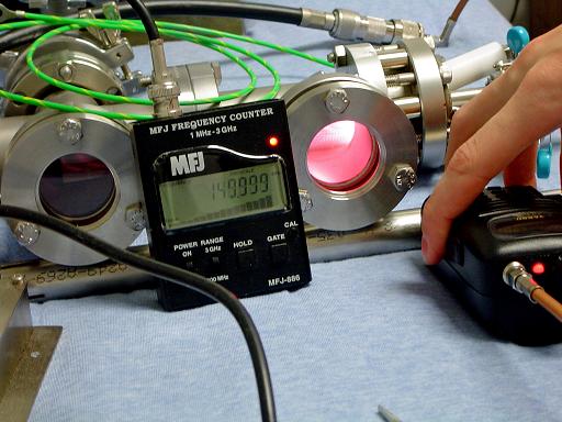 |
Injector ICP test (5/25/2007) Injector successfully ionizes under 150MHz ICP excitation. Injector was driven at 20W, with 5W reflected since the matching network and antenna were designed for 900MHz operation |
Assembly of final injector design (2/14/2008)
|
|
|
|
|
|
|
|
|
|
|
|
|
|
|
|
|
|
|
|
|
|
|
|
|
|
|
|
|
|
| Useful links: http://www.fusor.net/ Open Source Fusion Research Consortium. |
|
By attempting to reproduce any experiments or devices listed on this domain in part or in whole, you agree to hold me harmless against any lawsuit or liability. Copyright © 1998 - 2005 by Andrew Seltzman. All rights reserved. |
|
| Contact me at: admin@rtftechnologies.org | |