| IEC Fusion Reactor, Mark 1 |
 |
 |
 |
 |
 |
 |
 |
| Introduction: View the continuation of IEC research in the Mark 3 IEC fusion reactor. IEC fusion reactor Mark 1 project has officially ended(10/14/2005), never attaining detectable fusion. The main problem was the low conductance vacuum tubing and leaks in the core which prevented the reactor from obtaining the required 1-10mTorr operating vacuum. The vacuum levels present allowed for greater ionization current then the power supply could source, overloading the transformer and dropping the grid potential to 3kV, considerably lower then the 15kV required to obtain detectable fusion. While the Mark 1 reactor did not achieve fusion, it did create a number of well built reactor support system design, including a professional vacuum system, a neutron detector, computer interface systems, power control systems, and one of the first practical heavy water electrolysis units usable on an amateur IEC fusion system. IEC research will continue on the Mark 2 and Mark 3 reactor systems, which will have welded hemispherical core halved connected with conflat flanges to insure a hard vacuum seal. All components from the Mark 1 project will be reused on these reactors, with the exception of the neon sign transformer and the Mark 1 core. |
|
Overview: Inertial Electrostatic Confinement (IEC) Fusion is a unique concept developed
by Philo T. Farnsworth in the 1960’s. An IEC fusion reactor typically
consists of a geodesic inner grid that is held at a negative potential
surrounded by a grounded spherical vacuum envelope (outer “grid”).
The inner grid emits electrons that are accelerated towards the outer
grid by the voltage potential. The emitted electrons ionize deuterium
atoms in the sphere by colliding with their electrons which are freed.
The ionized deuterium is accelerated towards the center grid by the potential
difference.
|
|
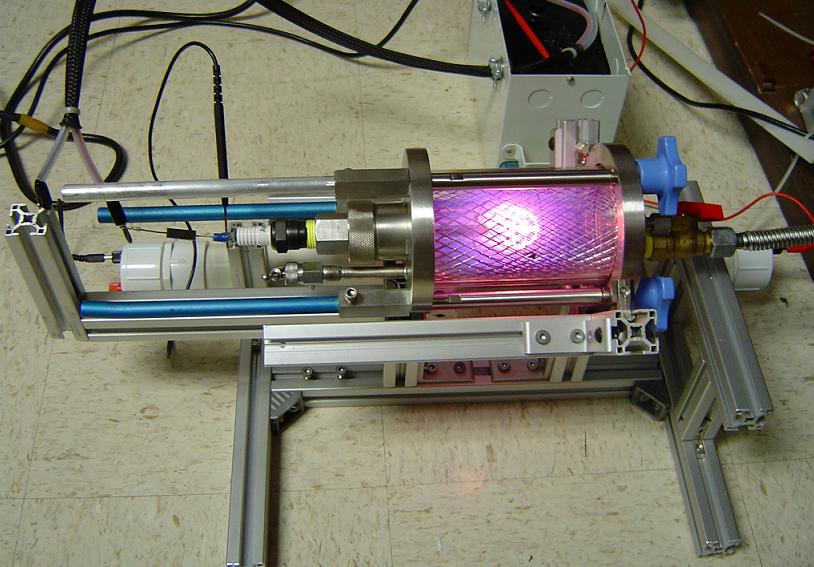
IEC Fusion Reactor: Early test run. |
|
 |
|
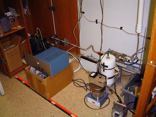 |
IEC Fusion Reactor: Current Setup (updated 2/11/2005). |
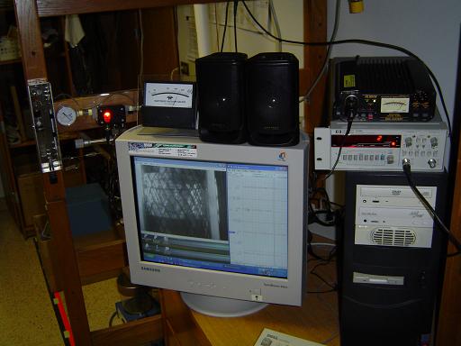 |
IEC Fusion Control Station: Control station for fusor. Controls vacuum, power, gas handling, and neutron detection (updated 2/11/2005). |
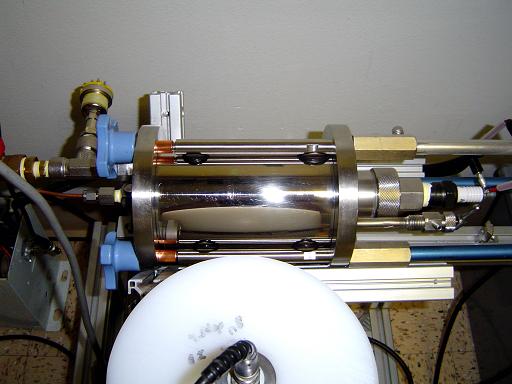 |
Reactor Core: The reactor core vacuum chamber was constructed out of a millipore filtration device. The original plastic cylinder used as the chamber walls was damaged by ion bombardment and was replaced with a stainless steel cylinder fabricated out of an exhaust tip. The stainless chamber greatly increased vacuum, and decreases outgassing. The rear of the chamber has a 1.25" ID tubulation, with an o-ring seal, that is used to attach the high voltage feedthrough. (updated 4/17/2005). |
 |
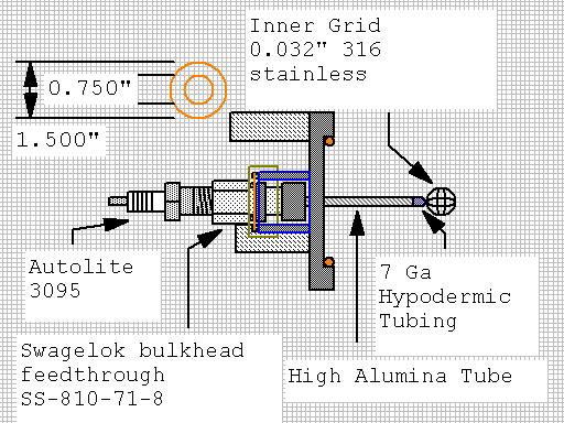
IEC fusion reactor core CAD This is a cad of the fusion reactor core. |
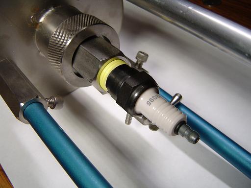 |
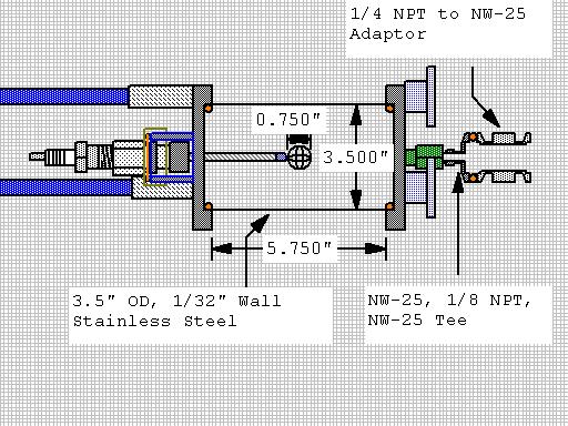
High Voltage Feedthrough: The high voltage feedthrough is designed to allow the 1/2 mpt thread on an Autolite 3095 sparkplug to interface with the chamber and provide a good vacuum seal. The sparkplug used is the Autolite 3095. This is a non-resistor plug and presents a 1/2" pipe thread for connection.
|
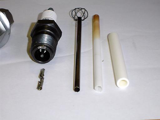 |
The internal ceramic standoff is long and unobstructed, allowing a high alumina ceramic rod to easily fit over the center electrode and provide excellent insulation. The conductor is fabricated from a #7 gauge stainless steel hypodermic tubing press fitted over a Radio Shack female molex crimp pin. The crimp pin fits snugly over the center pin of the sparkplug and holds the rod in place. Ceramic rod insulates steel HV support stalk, while withstanding ion bombardment. |
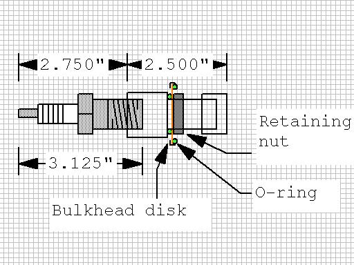 |
Feedthrough CAD: The Autolite 3095 is screwed into the Swagelok SS-810-71-8 bulkhead feedthrough and sealed with teflon tape. The feedthrough seals to the bulkhead disk with an o-ring(green) and is held in place by the retaining nut. A centering ring positions the bulkhead disk(orange) and chamber o-ring(green) so that they seal against the chamber tubulation(blue) when the threaded end cap(yellow) is tightened.
|
 |
|
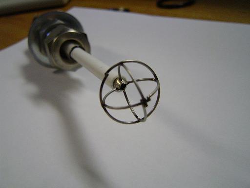 |
Inner Grid (Geodesic Type, welded 316 SS): The inner grid is constructed by spot welding 3 perpendicular rings of 316 stainless steel wire (0.032" thickness) into a geodesic grid. The mass of the grid, combined with the high transparency provide superior transparency and excellent plasma focus. High alumina high temperature ceramic insulator provides insulation to HV feed stalk while withstanding contact with high temperature plasma. |
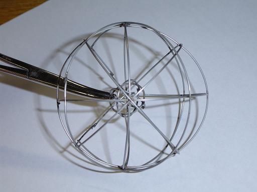 |
Outer Grid: The inner grid is constructed by spot welding 7 rings of 316 stainless steel wire (0.032" thickness) into a geodesic form. Outer grid is shown with inner grid held in approximate position The grid is 2.75" in diameter. |
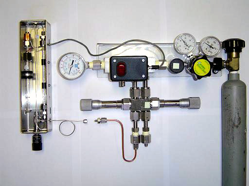 |
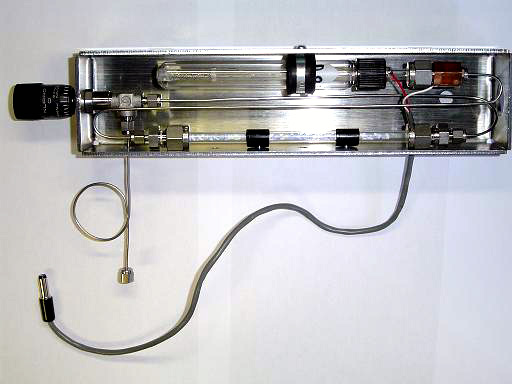
Deuterium Gas Handling System: Flow rate regulating system to meter deuterium gas into reactor core. Argon used for manifold purge. |
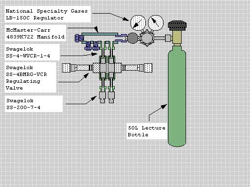 |
Deuterium Manifold CAD: Deuterium gas is produced in electrolysis assembly and metered into manifold. Micrometer regulating valves control the deuterium flow rate into the reactor. Extra ports will be used for deuterium supply to ion injectors in future upgrades and pressure metering equipment. |
 |
Deuterium Manifold CAD:
|
 |
Deuterium Manifold CAD:
|
 |
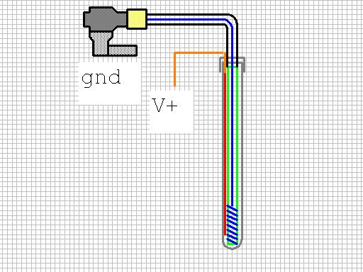
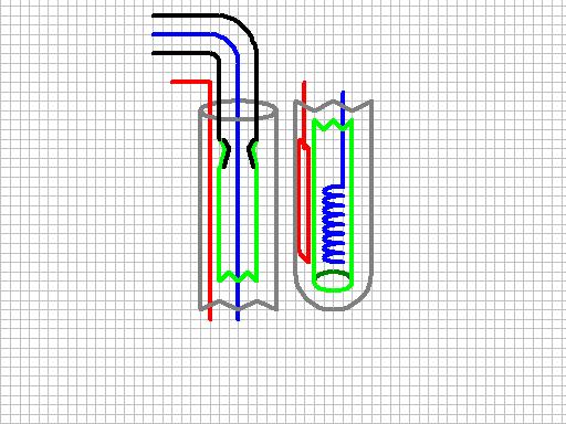
Deuterium Supply: Heavy water is electrolyzed to form deuterium and oxygen. The deuterium is then transferred to the reactor. This electrolysis assembly is enclosed in a centrifuge tube that contains the heavy water. |
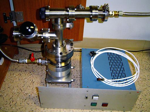 |
Vacuum System: The reactor system is pumped down with a Sargent Welch 3135 turbomolecular pump backed by a Sargent Welch 1400 dual stage rotary vain vacuum pump. The reactor must be operated under high vacuum to obtain the required mean free path, or average distance between collisions, for the deuterium ions being accelerated through the central grid. Operation at lower vacuum levels would cause the deuterium ions to collide with ambient, unionized deuterium in the reactor before they acquired the required energy level for fusion to occur. |
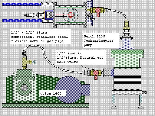 |
Vacuum system CAD:
|
| Useful links: http://www.fusor.net/ Open Source Fusion Research Consortium. |
|
By attempting to reproduce any experiments or devices listed on this domain in part or in whole, you agree to hold me harmless against any lawsuit or liability. Copyright © 1998 - 2005 by Andrew Seltzman. All rights reserved. |
|
| Contact me at: admin@rtftechnologies.org | |