| Sargent-Welch 3135 Turbomolecular Vacuum Pump Repair |
 |
 |
 |
 |
 |
 |
 |
| Overview: Documentation of the repair and cleaning of a Sargent-Welch model 3135 turbomolecular vacuum pump. A used older model turbo pump with no controller was acquired on ebay. A Sargent-Welch model was chosen due to it's simple motor control system. Initially the pump was contaminated with carbon deposits and mud from mud diver nests in the rotors. The backing flange was broken and some aluminum parts were corroded. Later a matching controller was also acquired on ebay and repaired allowing the turbo pump to run with the original controller. |
|||||||||||||||||||||||||||||||||||||||||
 |
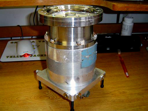
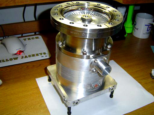
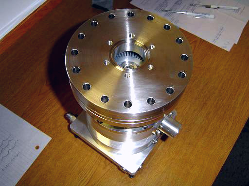
Sargent-Welch 3135 turbo pump. |
||||||||||||||||||||||||||||||||||||||||
Sargent-Welch model 3135 turbomolecular vacuum pump:
|
|||||||||||||||||||||||||||||||||||||||||
Pump Specifications:
|
|||||||||||||||||||||||||||||||||||||||||
|
|
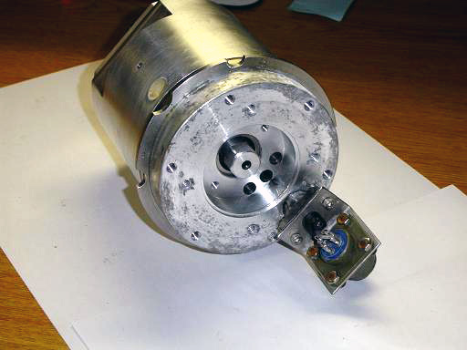
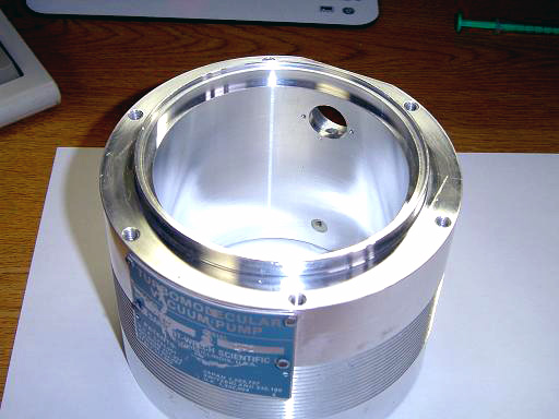
Sargent-Welch model 3135 turbomolecular vacuum pump: Pump shows corrosion and scratches. Motor control unit is missing but rotors spin freely and motor control scheme is simple. Motor is 3 phase. |
||||||||||||||||||||||||||||||||||||||||
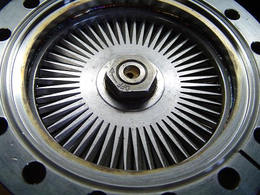 |
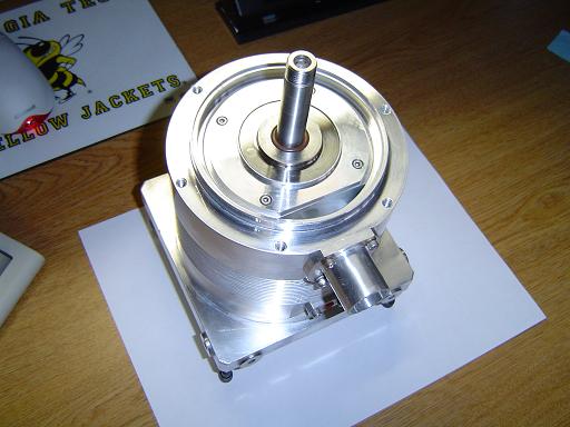
Top rotor: Top rotor is 3.75" in diameter, main flange is 6" OD conflat. Retaining nut is left hand threaded to prevent loosening during pump operation. Note mud diver nest in shaft. |
||||||||||||||||||||||||||||||||||||||||
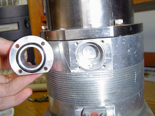 |
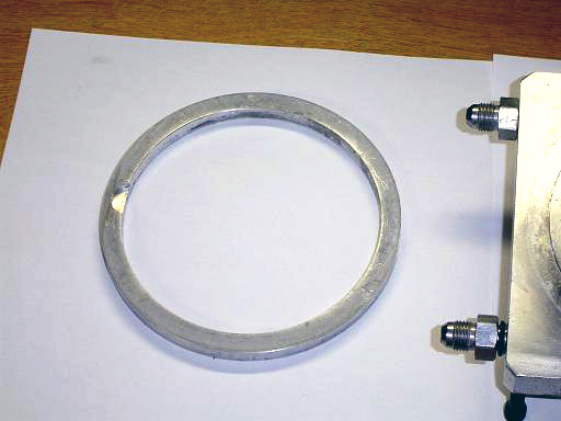
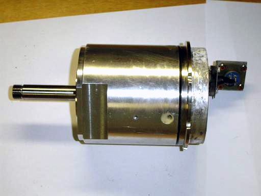
Backing flange: Initially a NW flange, however the aluminum ring has broken off. The outer diameter of the aluminum tube is 1". |
||||||||||||||||||||||||||||||||||||||||
|
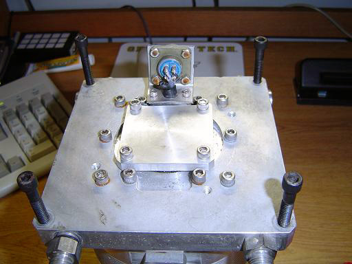
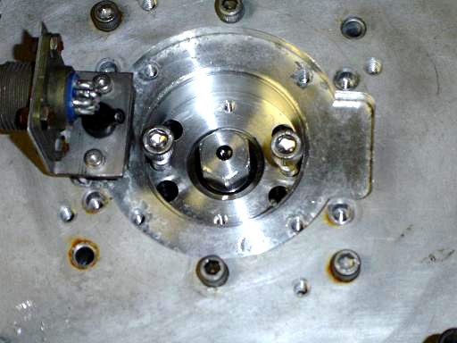
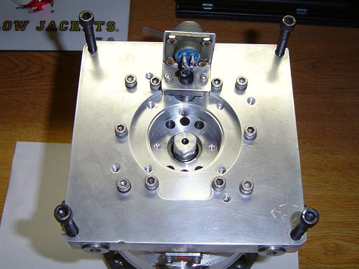
Pump base: Base shows some signs of corrosion. Square block in the middle creates a vacuum seal to the motor base. Connector has 4 pins, 3 for motor drive, one for case ground. |
||||||||||||||||||||||||||||||||||||||||
 |
Pump base: Vacuum seals removed, o-ring is compressed against bottom face of motor. Motor and pump case are attached to base plate. |
||||||||||||||||||||||||||||||||||||||||
 |
Rotor lock: Rotor assembly provides mechanism for locking shaft in place to loosen retaining nut. Two 1/4" bolts drop into locking holes in motor. |
||||||||||||||||||||||||||||||||||||||||
 |
Retaining nut: Retaining nut and washer are removed, rotor assembly is now free. |
||||||||||||||||||||||||||||||||||||||||
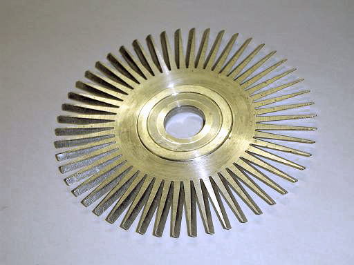 |
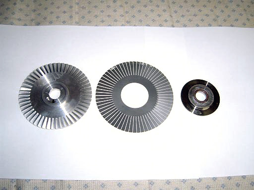
Top rotor: Top picture of top rotor. |
||||||||||||||||||||||||||||||||||||||||
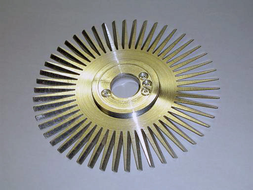 |
Top rotor: Bottom picture of top rotor, holes drilled to balance rotor. |
||||||||||||||||||||||||||||||||||||||||
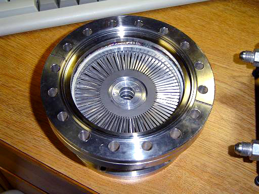 |
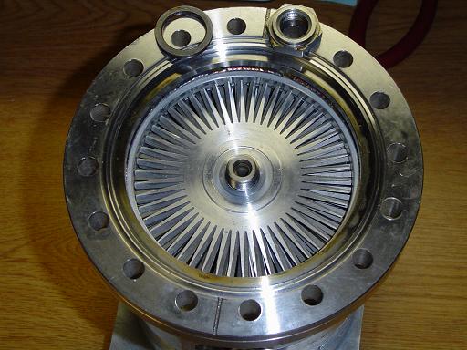
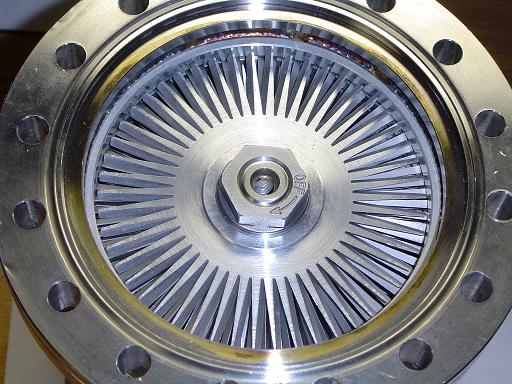
Rotor assembly: Top picture of rotor assembly. Top set of fixed stator blades visible. |
||||||||||||||||||||||||||||||||||||||||
 |
Rotor assembly: Bottom picture of rotor assembly. Bottom set of fixed stator blades visible. Blade angle is lower and blades start closer to edge. |
||||||||||||||||||||||||||||||||||||||||
 |
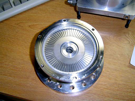
Pump base: One rotor and stator visible. |
||||||||||||||||||||||||||||||||||||||||
 |
Base rotor: Base rotor, stator, and bearing guard. |
||||||||||||||||||||||||||||||||||||||||
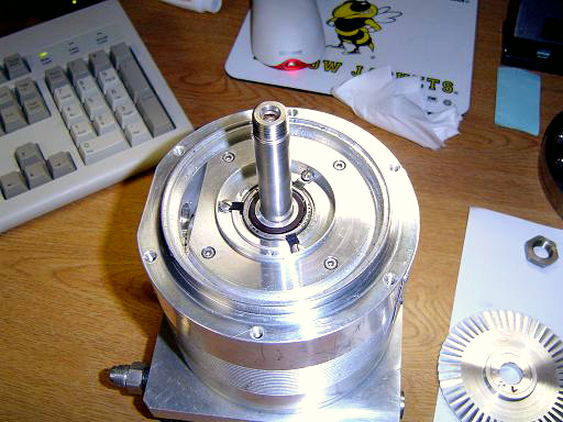 |
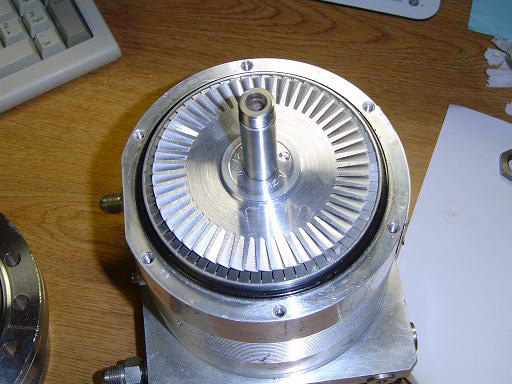
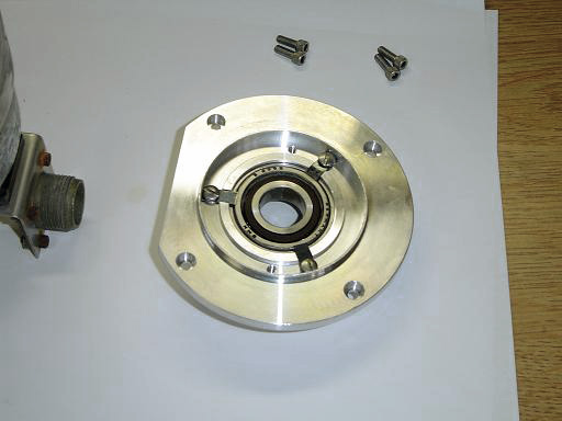
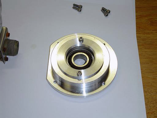
Pump motor: Motor face visible, high speed bearing supports shaft. |
||||||||||||||||||||||||||||||||||||||||
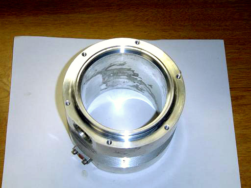 |
Pump case: Sealed against motor with an o-ring, provides heat distribution and connection to backing flange. |
||||||||||||||||||||||||||||||||||||||||
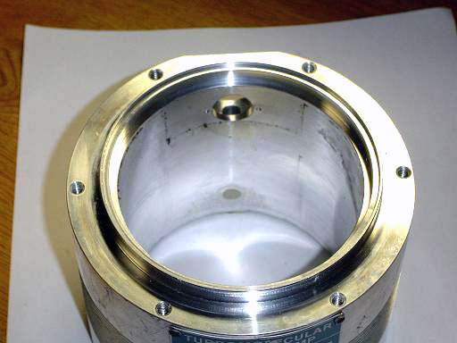 |
Pump case: Backing flange connection interior. |
||||||||||||||||||||||||||||||||||||||||
 |
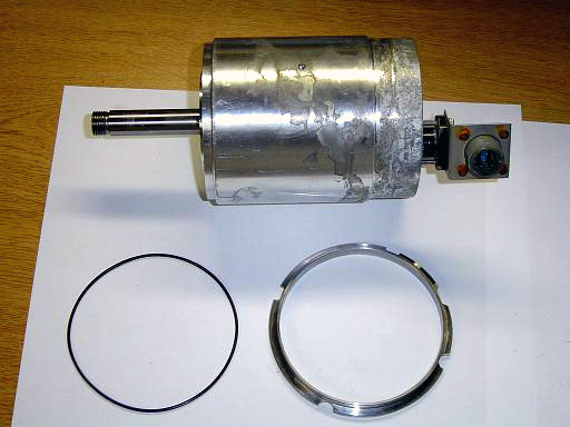
Support ring: Positioned between the pump case and the base plate. |
||||||||||||||||||||||||||||||||||||||||
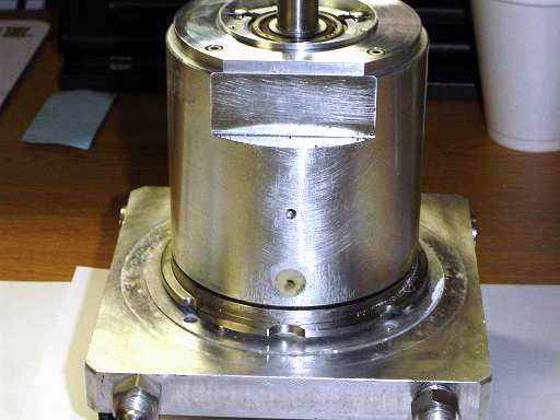 |
Mounted motor: Notch in side is for internal clearance of the backing flange. O-ring seals against pump case. |
||||||||||||||||||||||||||||||||||||||||
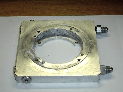 |
Base plate: Top picture of base plate. Set screws compress o-ring to create vacuum seal. |
||||||||||||||||||||||||||||||||||||||||
 |
Base plate: Bottom picture of base plate. |
||||||||||||||||||||||||||||||||||||||||
 |
Motor: Bottom of motor shows corrosion, control connector visible. |
||||||||||||||||||||||||||||||||||||||||
 |
Motor: Side view of motor. O-ring and compression assembly attached. |
||||||||||||||||||||||||||||||||||||||||
 |
Vacuum Seal: O-ring and compression assembly removed. |
||||||||||||||||||||||||||||||||||||||||
 |
Top bearing: Top view of top motor bearing |
||||||||||||||||||||||||||||||||||||||||
 |
Top bearing: Bottom view of top motor bearing |
||||||||||||||||||||||||||||||||||||||||
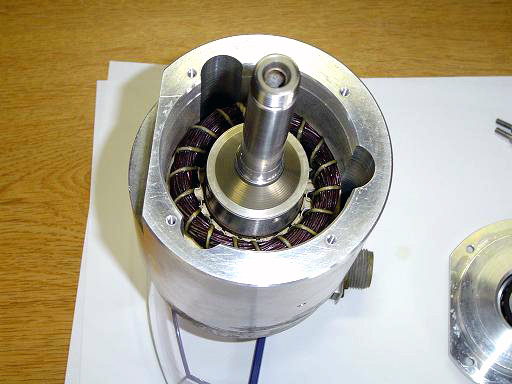 |
Motor: View of motor interior showing rotor and three phase stator. |
||||||||||||||||||||||||||||||||||||||||
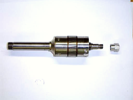 |
Rotor: Rotor and bottom retaining nut. |
||||||||||||||||||||||||||||||||||||||||
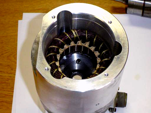 |
Motor: View of motor interior showing three phase stator. stator has 18 poles. |
||||||||||||||||||||||||||||||||||||||||
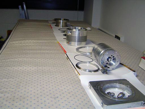 |
Parts: Lineup of parts before cleaning. |
||||||||||||||||||||||||||||||||||||||||
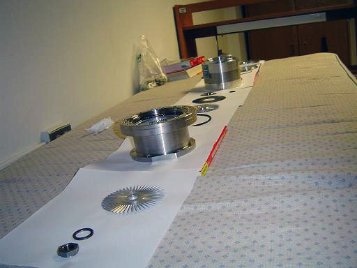 |
Parts:
Lineup of parts before cleaning. |
||||||||||||||||||||||||||||||||||||||||
| Cleaning and Repair Process: Corrosion on aluminum parts was polished off aluminum components using an emory cloth. Aluminum oxide and grit was cleaned off using toothpaste. Parts were then cleaned with soap and washed. The lip left by the broken off NW flange was filed down and polished with emory cloth leaving a smooth 1"od tubulation as the backing connector The rotor assembly was washed with soap and water. The top surface of the top rotor was polished with 1.5micron lapping film. |
|||||||||||||||||||||||||||||||||||||||||
 |
Motor: Corrosion polished off with emory cloth. Bearings re-lubricated and o-rings re-grease. Motor has been re-coated with vacuum grease to provide thermal contact with pump case. |
||||||||||||||||||||||||||||||||||||||||
 |
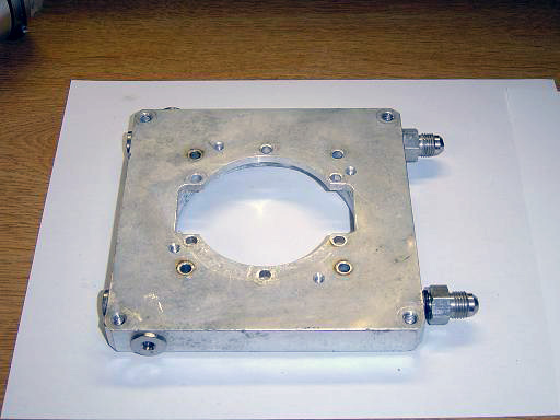
Mounted motor: Motor mounted on cleaned base plate. |
||||||||||||||||||||||||||||||||||||||||
 |
Pump Case: Cleaned pump case. |
||||||||||||||||||||||||||||||||||||||||
 |
Motor: Mounted motor with bearing guard and backing flange in place. |
||||||||||||||||||||||||||||||||||||||||
 |
Pump base: Vacuum seals cleaned and ready for installation on motor. |
||||||||||||||||||||||||||||||||||||||||
 |
Top Rotor: Cleaned top rotor and retaining nut. |
||||||||||||||||||||||||||||||||||||||||
 |
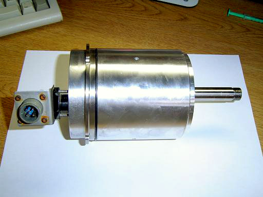
Turbomolecular vacuum pump: Pump cleaned and ready for operation. |
||||||||||||||||||||||||||||||||||||||||
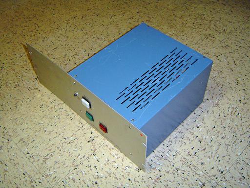 |
Controller: Sargent-Welch 3134 PS. This controller is a variable frequency drive using a 6 transistor 3-Phase inverter. |
||||||||||||||||||||||||||||||||||||||||
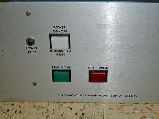 |
Controller Front: Power and reset buttons. |
||||||||||||||||||||||||||||||||||||||||
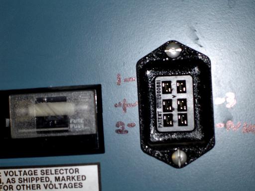 |
Connector: Connector for turbo pump.
|
||||||||||||||||||||||||||||||||||||||||
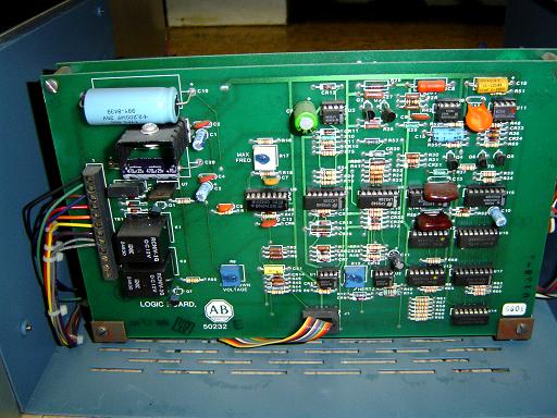 |
Logic Control Board: An Allen-Bradley 50232 logic board provides the PWM synthesis required to run the drive. |
||||||||||||||||||||||||||||||||||||||||
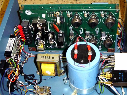 |
Drive Control Board: An Allen-Bradley 50231 control board contained the high power switching darlingtons to generate a 3-phase PWM. The bottom right darlington (PTC6072) was burnt out, rendering the controller inoperative. |
||||||||||||||||||||||||||||||||||||||||
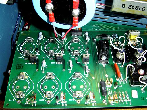 |
Darlingtons Removed: All darlingtons were removed from controller board for testing. |
||||||||||||||||||||||||||||||||||||||||
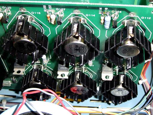 |
Drive Board Repaired: Top right darlington was moved to replace the bottom right darlington. The top darlington was then replaced with an NTE99. Heat sinks were added to darlingtons. The top right darlington driver was damaged by the fault with the bottom darlington, and was also replaced. |
||||||||||||||||||||||||||||||||||||||||
 |
Adaptor Flange: 6" CF to 2.75" CF adaptor flange. Sealed with viton o-ring. |
||||||||||||||||||||||||||||||||||||||||
|
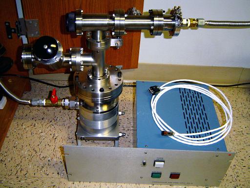
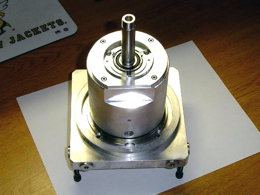
Restored Turbo Pump:
|
||||||||||||||||||||||||||||||||||||||||
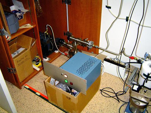 |
Turbo Pump Operational: Turbo pump spins up with repaired controller to operation speed. |
||||||||||||||||||||||||||||||||||||||||
By attempting to reproduce any experiments or devices listed on this domain in part or in whole, you agree to hold me harmless against any lawsuit or liability. Copyright © 1998 - 2005 by Andrew Seltzman. All rights reserved. |
|
| Contact me at: admin@rtftechnologies.org | |