| Electrostatic Particle Accelerator |
 |
 |
 |
 |
 |
 |
 |
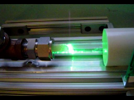
| Overview: This is a small electrostatic particle accelerator, built in my senior year of high school(2002-2003). It is designed for electron acceleration. Power is provided by a Van de Graaf generator or Cockroft Walton multiplier; electrons are transferred to the sphere until the charge becomes sufficient to ionize air and the charge jumps between the sphere and the discharge terminal. The discharge terminal is connected to the cathode section of the accelerator where a thin copper wire conveys the electrons to its pointed tip inside a glass tube. Vacuum in the tube is 1.5E-5 torr; created by a Sargent-Welch 1400 rotate vane pump coupled to a CVC PMC-2 oil diffusion pump (105 L/s, 300w, running LDS-705 oil). Vacuum seals are swagelok fittings with the metal ferrules replaced with Teflon ferrules that are coated with the diffusion pump oil. There the electrons are accelerated down an evacuated tube by a 100,000 v potential difference to a grounded terminal. A ZnS coated (same as green screen computer monitors) paper screen is inside the tube. When the electrons collide with the screen, it gives off green light to prove operation. |
|||
| Principle: Particle accelerators are designed to impart kinetic energy on charged particles by means of an applied electric field. When a charged particle is subjected to an electric field it experiences a force proportional to the magnitude of the field, and therefore an acceleration. Once the particles have gained a sufficient amount of energy they are collided with other particles (either matter or anti-matter) and the particles resulting from the collision is observed by a detector array. |
|||
| Design: The design of this accelerator focused on creating a simple yet robust accelerator platform capable of imparting a relativistic velocity on sub-atomic particles and small ions. The design of the vacuum system focused on the capability of achieving an operating level of vacuum (1.5E-5 torr) in under 2 hours and the ability to cycle from on at full vacuum to off at atmospheric pressure within 30 minuets as well as a high degree of reliability with minimal servicing. |
|||
 |
|||
|
|
100Kev pulsed operation with Cockroft Walton multiplier: These are frame grabs from a digital video of the accelerator running with the Cockroft Walton multiplier supplying 100kv pulses through a spark gap. |
||
|
|
100Kev pulsed operation with Cockroft Walton multiplier: |
||
|
100Kev pulsed operation with Cockroft Walton multiplier: |
||
|
|||
 |
|||
|
|
|||
 |
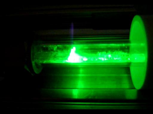
100Kev pulsed operation with Van De Graaf generator: These are frame grabs from a digital video of the accelerator running, you can see the glow of the ZnS screen as well as the discharge to the pickup terminal that leads to the cathode contact. Note that sometimes you can not see the discharge due to it being out of sync with the capture rate of the digital camera. |
||
|
|
|||
 |
100Kev pulsed operation with Van De Graaf generator: |
||
|
|||
100Kev pulsed operation with Van De Graaf generator: |
|||
|
|||
|
100Kev pulsed operation with Van De Graaf generator: |
||
|
|||
Accelerator CAD designs: |
|||
|
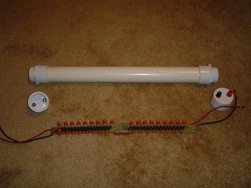
Accelerator parts: |
||
 |
Frame: The accelerator's frame is made of a 1.25x2x56" aluminum I-channel attached to two 24" 8020, 1010 aluminum extrusions. The I-channel has four 1/4" holes drilled down the center of the channel in the positions indicated in the CAD design. The beam line shield has corresponding holes drilled to match these positions; 1/4" holes at the bottom of the shield, 5/8" at the top of the shield. Nylon bolts are lowered in from the top of the shield, through the bottom of the shield and the I-channel where they are fastened at the bottom with nylon bolts. The two 8" long side structures are attached by two l-brackets at each end. They protect the vacuum system and can be used to carry the accelerator since they are located exactly at it's center of mass. |
||
 |
Frame Bolts: The main I-channel provides structural support to the beam line guard and attaches it to the 8020. The I-channel and 8020 extrusions have 1/4" access holes drilled in them at 1" and 8" from the end, additionally the I-channel has places for the t-nuts cut out in it. The heads of 0.75" long hex-head bolts are inserted into the channels of the 8020 and aligned to match the access holes. The bolts are then inserted into holes in the aluminum I-channel and the t-nuts are positioned in the vertically cut holes in the I-channel. The bolts are then tightened into the nuts using an allen key through the access holes. |
||
 |
Axial View: The beam line is centered in the shield by two foam inserts placed 10" inward of each side of the shield. The inserts are soft foam cylinders 1.5" diameter by 3" long with a 0.5" hole cut down the center. |
||
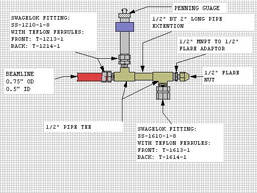 |
Vacuum Hub: The vacuum hub connects the diffusion pump to the beam line and penning gauge head as well as containing the aperture fitting. The hub is grounded through the frame and vacuum system and serves as the anode with respect to the negatively charged cathode. The hub will maintain a vacuum seal at 1.5E-5 torr while allowing quick connection / disconnection of components.
|
||
The pipe fitting are brass and the swagelok fittings are stainless steel with the steel ferrules replaced with Teflon ferrules. These ferrules are coated with diffusion pump oil which when compressed against the walls of connecting components by the nut, ensures a near perfect vacuum seal with only hand tightening. The aperture fitting is comprised of a 1/2" mnpt to 1/2" flare adapter and a 1/2" flare nut compressing a 5 micron thick disk of copper. The edges of the disk are bent over the adapter by the nut and compressed such that forms a vacuum seal. However the thickness of the disk attenuates most of the electrons that collide with it and very few pass through. The pieces of the vacuum hub interconnect with pipe threads. The threads are wrapped in 6 layers of teflon tape. the threads are screwed together while one piece is held in a vice and the other is torqued with an 18" adjustable wrench until the teflon tape fuses together from the pressure and seals against the walls. For added vacuum sealing the excess teflon tape outside the threads is cut off and diffusion pump oil is injected into the intersection of the fittings so that any remaining microscopic leaks are blocked by the oil. These modifications to the normal method of plumbing is what enables this system to achieve a vacuum level of 1.5E-5 torr. |
|||
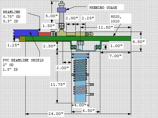 |
Vacuum System Mounting Diagram: The vacuum system mounting diagram shows interconnection and placement of high vacuum components. The diffusion pump has 3 bolt holes in the top of the flange adapter where two aluminum mounting plates are attached for mounting the pump. There two plates are connecter to two 4" 8020 extrusions that are attached to the main frame using 4 l-brackets; one at each corner. The flange adapter is mounted to the diffusion pump flange with 6 bolts and is sealed with an aluminum/rubber o-ring. The adapter terminates in a 2.25" long 1" OD stainless steel pipe. The Vacuum Hub's bottom swagelok fitting mounts on to this pipe, securing the hub in place and creating a vacuum seal. The diffusion pump was connected directly to the beam line to increase pumping speed. Likewise a baffle was not utilized in order to increase pumping speed, however the oil back streaming that a baffle usually prevents is nearly nonexistent due to the high grade of diffusion pump oil used (LDS-705). |
||
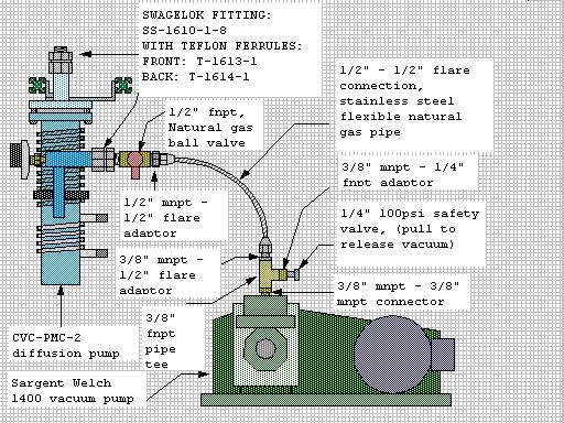 |
Backing Vacuum Connections: The diffusion pump is backed by a Sargent Welch 1400 dual stage rotary vain vacuum pump. The welch pump initially pumps the beam line down to 20 torr at which point the diffusion pump is turned on and pumps the system down to 1.5E-5 torr. The swagelok, flare adaptor, flexible stainless steel hose, and safety valve are stainless steel, the rest of the fittings are brass. The backing vacuum connections provide a means to adapt the backing pump to the diffusion pump as well as valves to release vacuum and isolate the diffusion pump / accelerator from the backing pump. All adaptors were cleaned in acetone and teflon pipe tape is used to provide a vacuum seal between the fittings.
|
||
The isolation valve is a natural gas valve from ace hardware. The valve's interior was cleaved with isopropanol to remove the grease originally used. This was replaced with diffusion pump oil to prevent contamination of the system. The flexible stainless steel hose was originally designed as a connector to natural gas appliances(dryer, water heater, etc.). The flare fittings are coated with diffusion pump oil to ensure a good vacuum seal. The safety valve is designed to release at high pressure, however it can be manually released by pulling on the attached ring. The utilization of the safety valve as a vacuum release provides a simple auto resetting, release mechanism with a minimal chance of accidental vacuum release during diffusion pump operation. |
|||
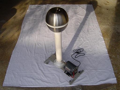
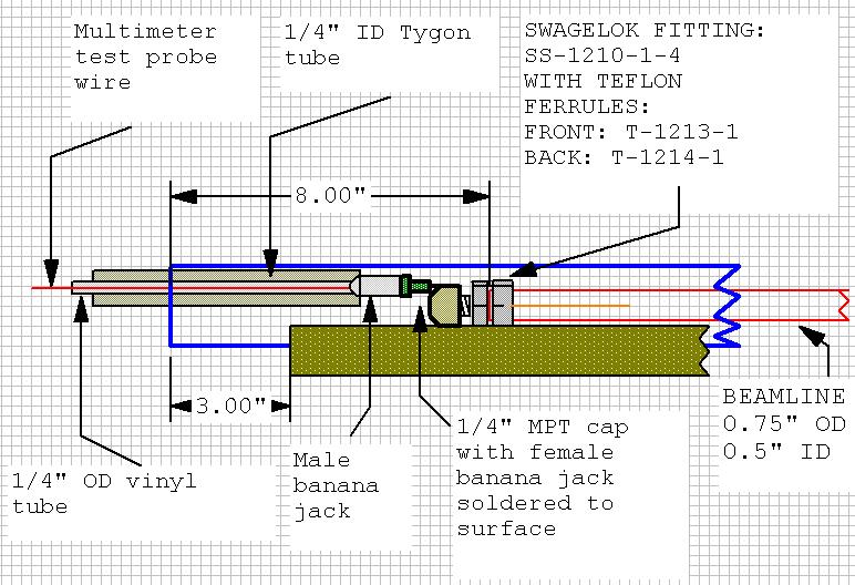
Cathode assembly: The cathode assembly is the source of the electrons that are being accelerated and is connected to the van de graaf generator's discharge terminal. The discharge terminal is a spherical (or hemispherical) conductor connected to the cathode by a high voltage cable. The high voltage cable is voltmeter test probe wire inside a 1/4" OD vinyl tubing that is inside 1/4"ID 1/2" OD tygon tube. The cable's total length is about 1.5m. at the end of the cable there is a male banana jack that connects to the accelerator. The accelerator's cathode section has a female banana jack soldered to the surface of a 1/4" npt pipe cap. This cap is connected to the 1/4" npt connector on the swagelok fitting (sealed with teflon pipe tape and diffusion pump oil). The swagelok fitting is stainless steel with the steel ferrules replaced with Teflon ferrules. These ferrules are coated with diffusion pump oil to seal against the beam line. The accelerator's cathode is a 8cm long 18ga copper wire connected to the swagelok fitting. The copper wire is inserted into an arc welder tip and bent into a loop behind it, securing it into place. The welder tip is wrapped in copper foil and press fitted into the swagelok fitting. |
|||
 |
|||
Useful Links:
|
|||
By attempting to reproduce any experiments or devices listed on this domain in part or in whole, you agree to hold me harmless against any lawsuit or liability. Copyright © 1998 - 2005 by Andrew Seltzman. All rights reserved. |
|
| Contact me at: admin@rtftechnologies.org | |