| IEC Fusion Reactor Mark 3 Test Runs |
 |
 |
 |
 |
 |
 |
 |
Overview: Reactor test runs Newer test runs with upgraded system |
|
 |
Test Run 0 (2/16/2008) Purpose: vacuum system test and leak check Result: No vacuum leaks in primary vacuum system System was pumped down to 5 mTorr with dual stage vacuum pump. |
 |
Test Run 1 (2/16/2008) Purpose: Power and cooling system test, cleaning of reactor core. Parameters:
Result: Power system and cooling system operational. Low power, low vacuum glow discharge in nitrogen plasma for preliminary testing of grid cooling system and power supply as well as cleaning of impurities in reactor core. |
| 2/21/2008 Reactor and support equipment moved from dorm room to radiation controlled zone (RCZ) in the nuclear engineering building for fusion tests. |
|
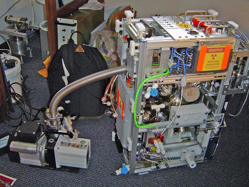
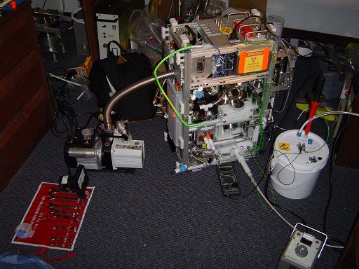
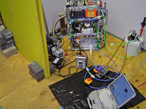
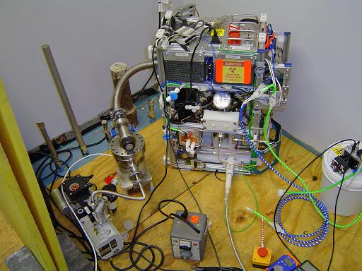
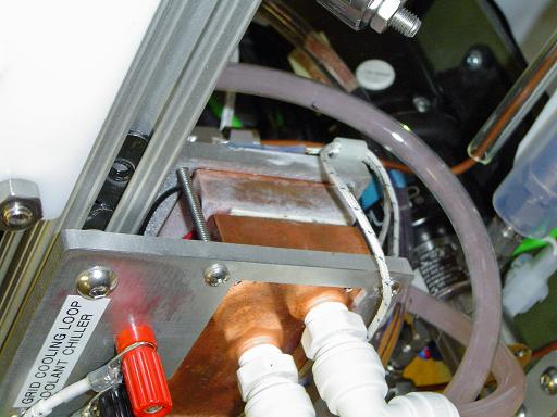
Reactor setup in RCZ
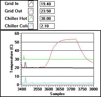
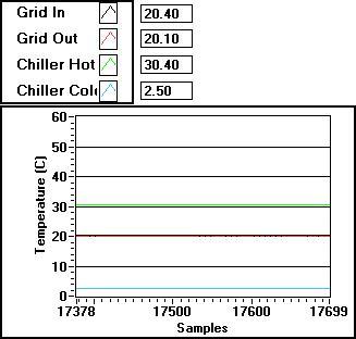
Grid temp 4.5kV, 40ma current (50ms/sample)
|
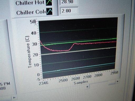
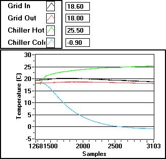
Test Run 2 (2/21/2008) Purpose: Test of reactor components after move to RCZ. Performance test on cooling system, preliminary test of control system. Parameters:
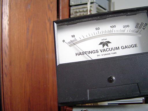
Result: Unfortunately the hastings DV-6M thermocouple gauge tube was broken in the move to the RCZ so vacuum levels were estimated from plasma appearance. Additionally, the grid feed through insulator vibrated loose during transport and slid down the stalk exposing the metal grid standoff to the plasma. Attempts to fix the insulator in situ were unsuccessful; the reactor core will have to be dismantled to reposition the insulator. The grid cooling system is a complete success, even under extreme thermal loading from the plasma (4.5kV, 40ma), the grid remained under 60C. At no load the chiller reached 2.5C indicating that switching to from 24V to 12V power on the chiller improved performance since the hot side doesn't overload the water cooling loop. Basic control system integration into the reactor has begun. Currently the computer can display cooling system temperatures, fluorinert coolant pressure and control the throttling valve over a USB link. The system is relatively unaffected by electrical noise emitted from the plasma, however sharp EMP spikes caused by sparks from the area of the grid stalk where the insulator vibrated loose can still cause the control system on board the reactor to lock up, requiring a power cycle to reset. The computer is unaffected by any electrical noise. |
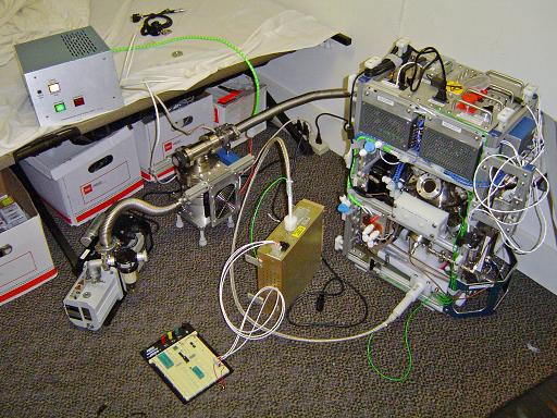
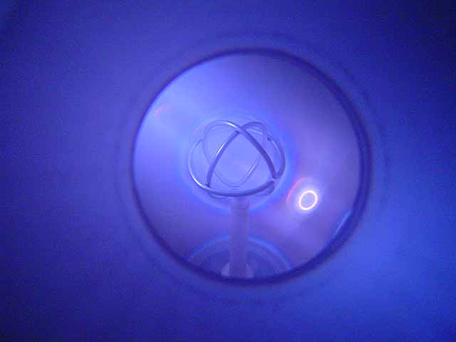
Reactor setup
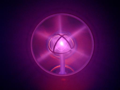
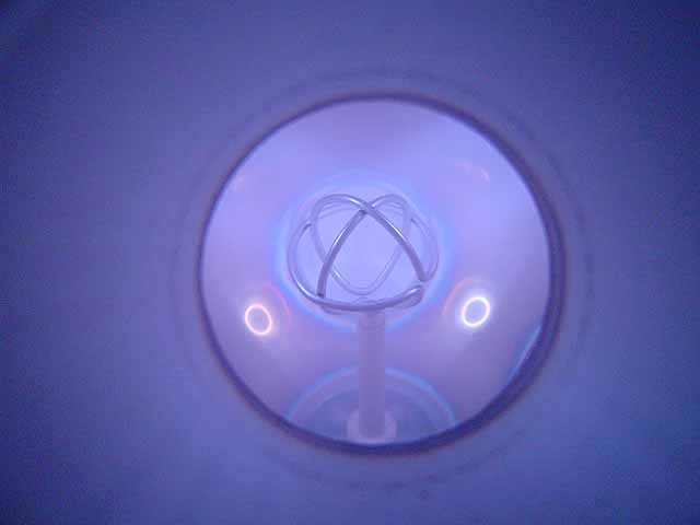
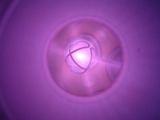
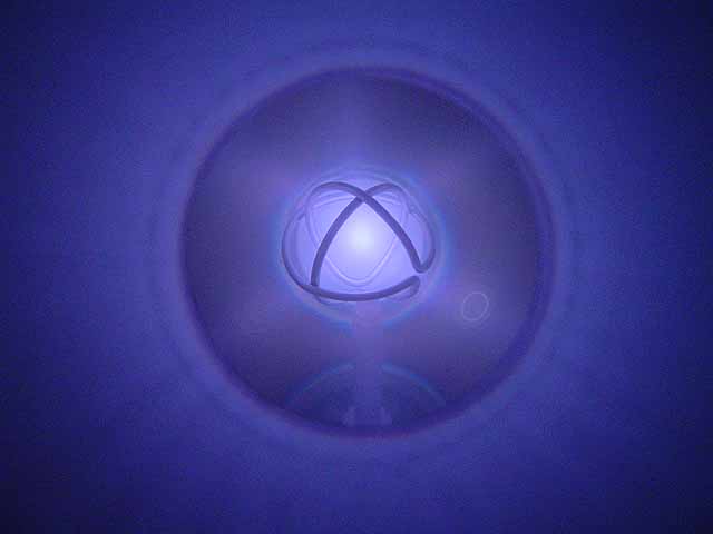
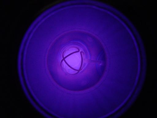
Deuterium plasma
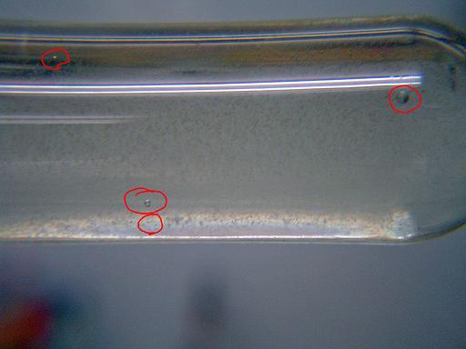
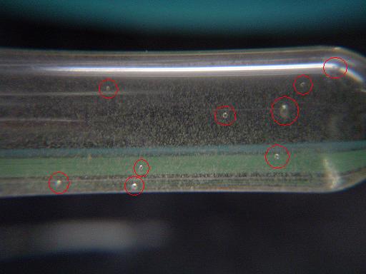
Neutron dosimeter detecting neutrons
|
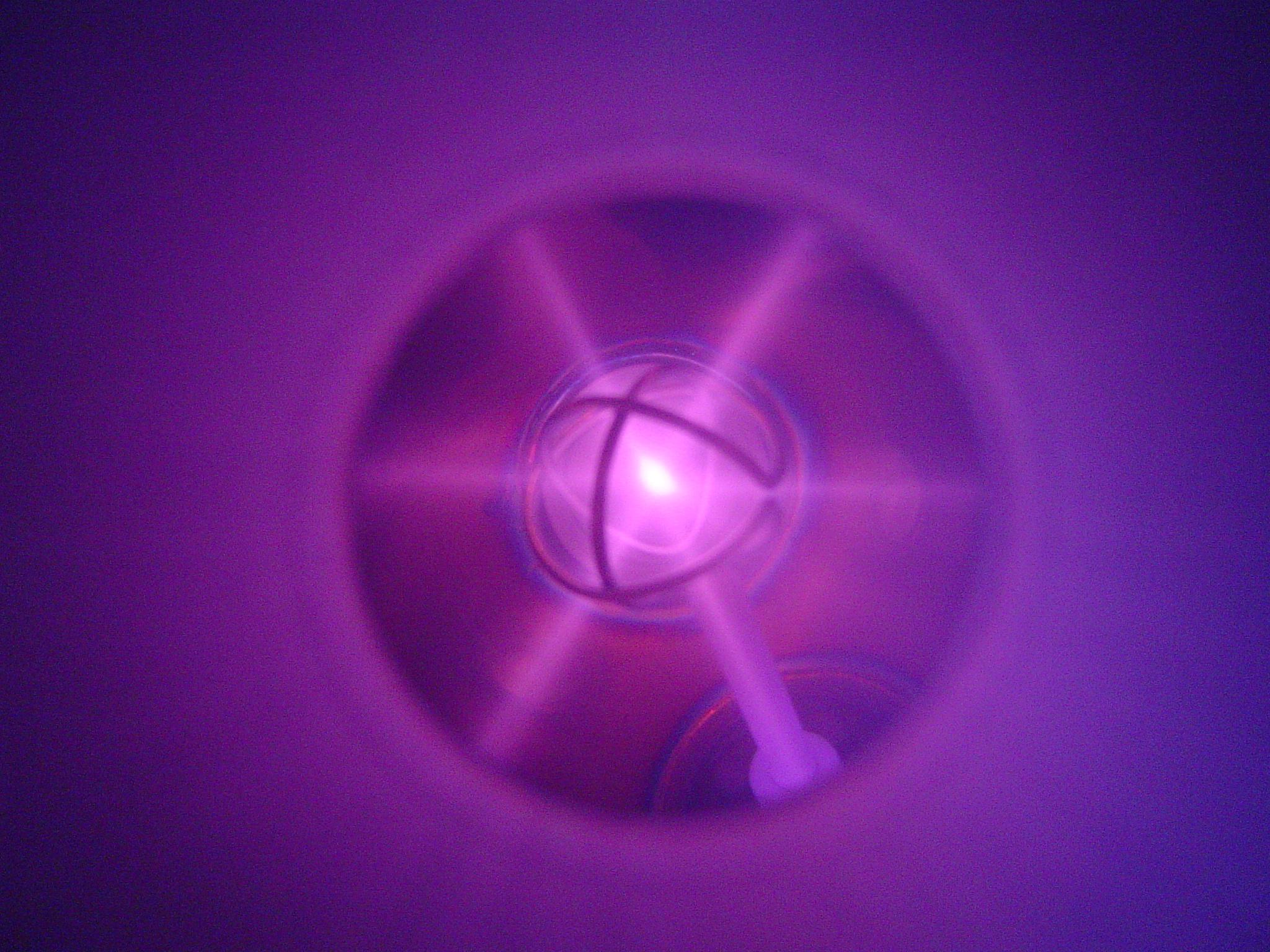
Test Run 3 (2/22/2008) Purpose: First fusion run with deuterium plasma, turbo pump connected to vacuum system. Parameters:
Result: Reactor operational, neutron output detected Reactor was operated with the turbo pump running and with deuterium supplied by the electrolyzer. The gas handling system was bypassed and the deuterium was feed directly into the core, regulated by the needle valve on the electrolyzer. The reactor was operated on and off over a period of approximately 45 minuets (approximately 15 minuets on time) after which 5 bubbles were observed in a BTI bubble neutron dosimeter with a sensitivity of 30 bubbles/mrem. 5 bubbles were observed after the run. The dosimeter was held against the reactor core during operation. The neutron output during the run was fairly low due to the low operating voltage and plasma impurities. During operation the viton o-ring was burnt by plasma, out gassing into the chamber and preventing operation at higher vacuum or voltage. This o-ring was initially used to allow the hemisphere shells to be electrically separate, however due to the plasma bombardment it will have to be shielded or replaced. The viton o-ring will be replaced with a copper o-ring as a short term solution, and will be replaced with a teflon o-ring that is shielded from the plasma during future tests that require the hemispheres to be electrically separate. The grid cooling system continued to perform optimally, maintaining the grid at approximately 18C during the run (at 7kV, 10mA). The grid remained cool during a brief test at 80mA current. The reactor exhibited low pressure instabilities due to the absence of an ion source. At full vacuum it was unable to generate a plasma even at 15kV on the grid. The ECRF injectors designed to solve this problem are still in construction. One complete design has been fully constructed, however it fails to operate due to capacitive coupling between the antenna coil and a metal part designed to hold the extractor cone in place.
|
| 2/22/2008 Reactor moved from RCZ to dorm room for insulator and o-ring repair as well as control system modification. The viton o-ring was replaced with a copper o-ring, the insulator was repositioned and modified to prevent it from sliding down due to vibration due to transporting the reactor on a dolly. |
|
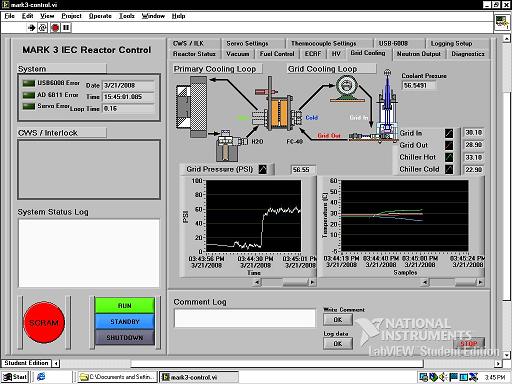 |
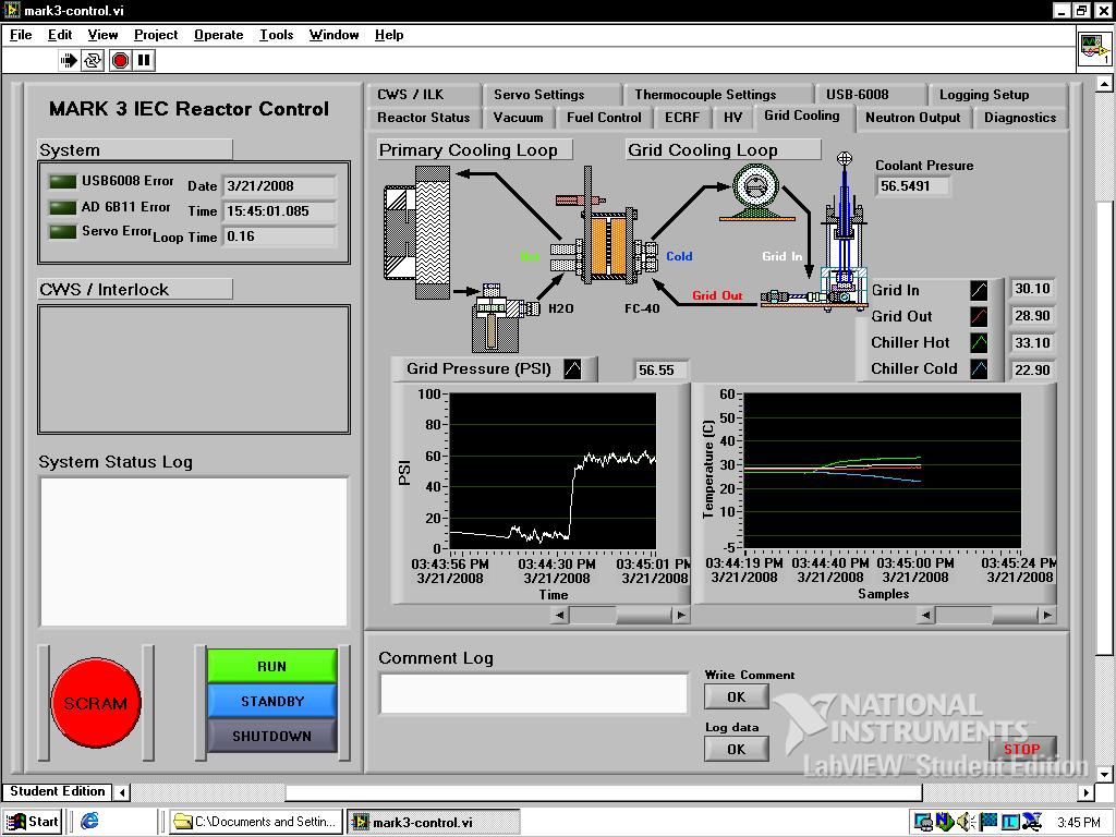
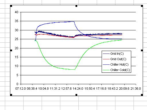
Test Run 4 (3/21/2008) Purpose: Control system / data acquisition test.
|
| 3/26/2008 Reactor and support equipment moved from dorm room to radiation controlled zone (RCZ) in the nuclear engineering building for fusion tests.
|
|
 |
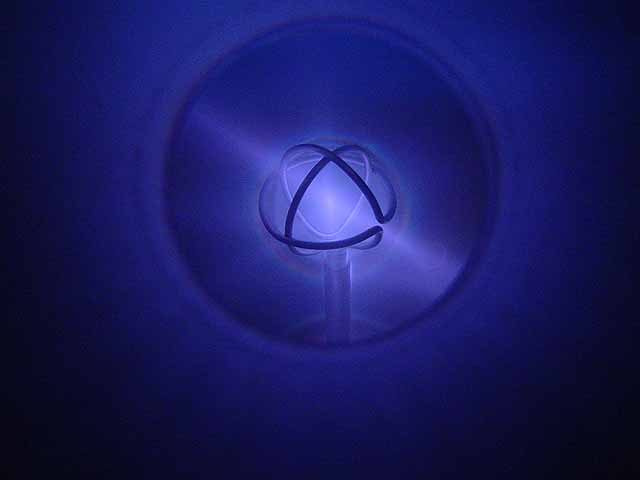
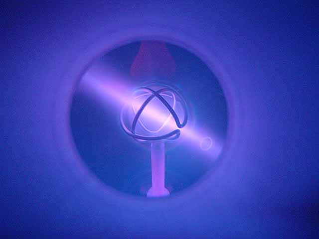
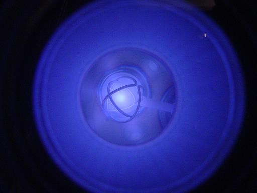
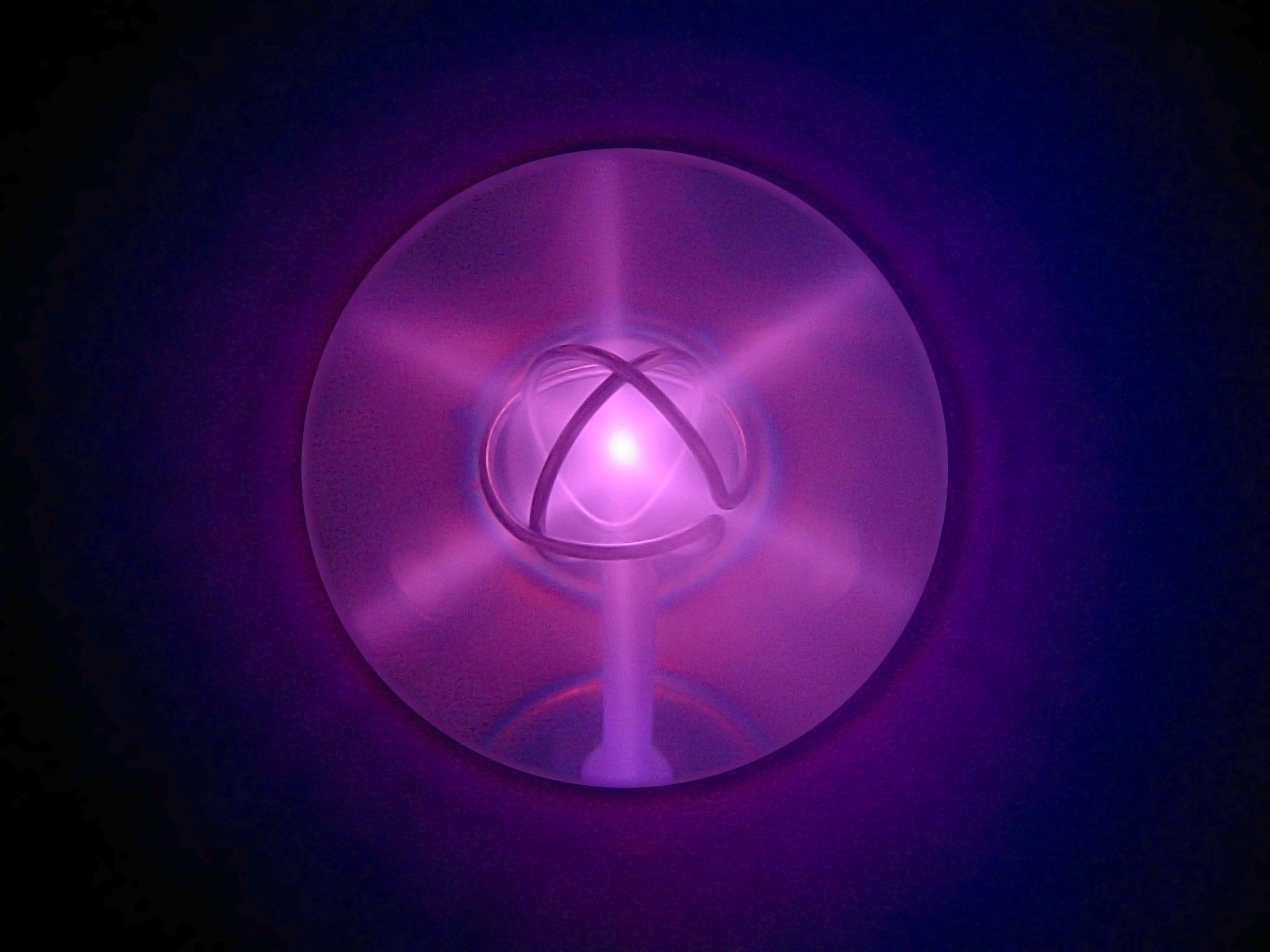
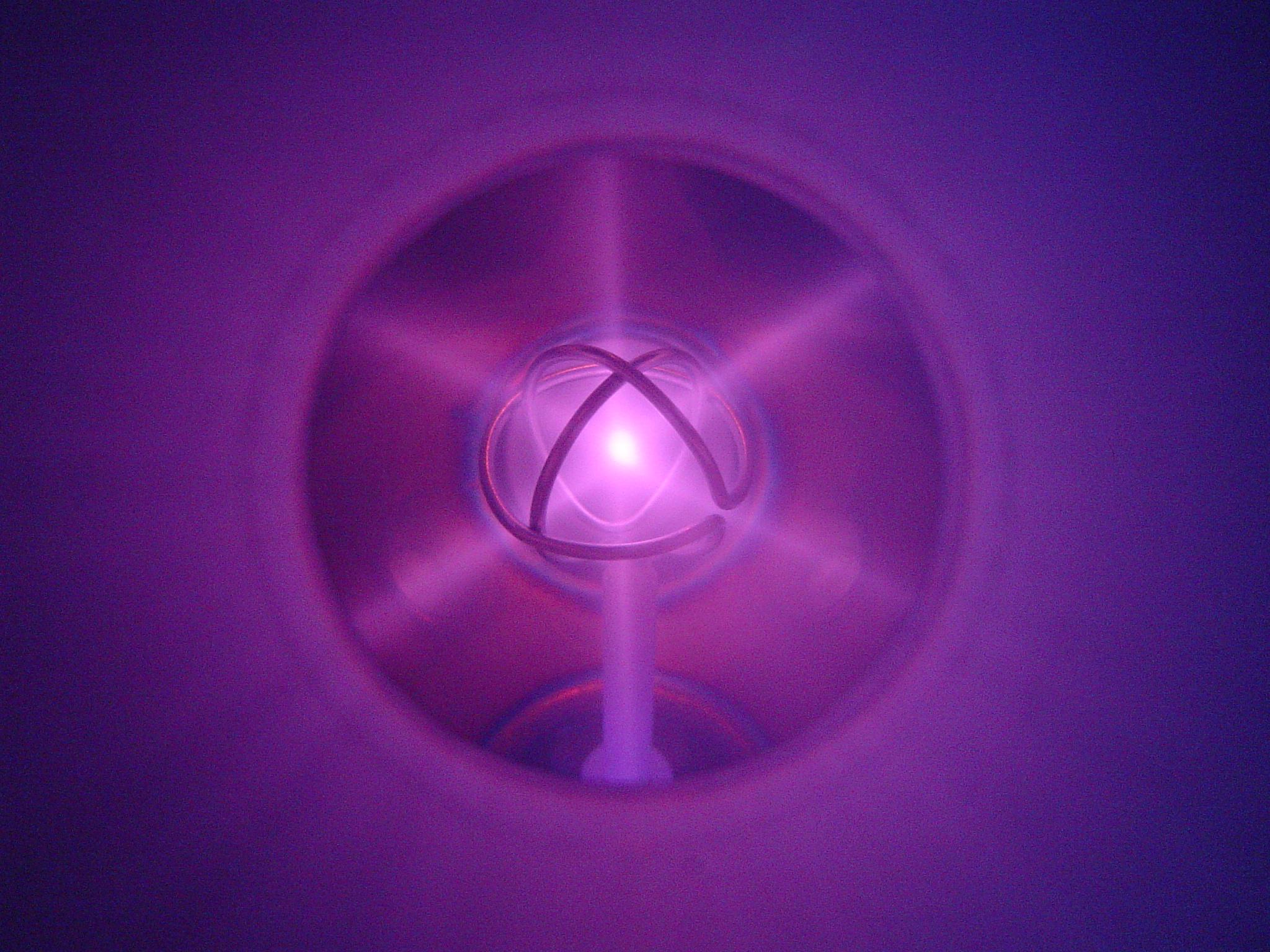
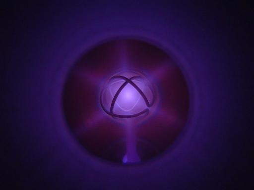
Test Run 5 (3/27/2008) Purpose: Data acquisition test Plasma image taken at 8kV, 4mA, 16mTorr, 4.4W grid load
|
 |
Test Run 6 (3/31/2008) Purpose: Data acquisition / fusion test and x-ray emission monitoring
|
 |
Test Run 7 (4/25/2008) Purpose: Low pressure test runs, increased power ion source.
|
june 2008 Reactor and support equipment moved to Madison, Wisconsin |
|
 |
Test Run 8 (8/17/2008) Purpose: Test spellman power supply and turbo pump cooling fan. Cooling fan added to turbo pump will allow lower operating temperatures and extended run time. Spellman power supply will provide a better regulated voltage source with current limiting. |
 |
Test Run 9 (5/14/2009) Purpose: Preliminary testing of ion injectors without grid potential. 8-10mTorr |
|
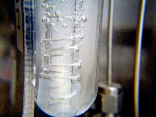
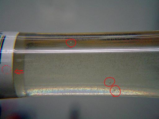
Test Run 10 (5/16/2009) Purpose: Preliminary testing of ion injectors with grid potential, 4mTorr, arcing along grid insulator Pics:
|
 |
Test Run 11 (8/13/2009) Purpose: Preliminary testing of ion injectors, arcing along grid insulator |
| Newer test runs with upgraded system | Newer test runs with upgraded system |
| Useful links: http://www.fusor.net/ Open Source Fusion Research Consortium. |
|
By attempting to reproduce any experiments or devices listed on this domain in part or in whole, you agree to hold me harmless against any lawsuit or liability. Copyright © 1998 - 2005 by Andrew Seltzman. All rights reserved. |
|
| Contact me at: admin@rtftechnologies.org | |