| IEC Fusion Reactor Mark 3 Optics System |
 |
 |
 |
 |
 |
 |
 |
Overview: A thompson scattering system will be used to measure plasma density at
the focal point. |
|
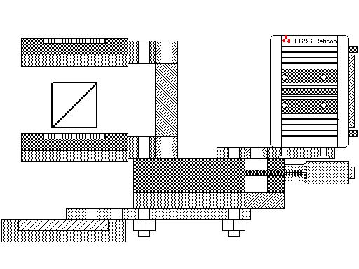 |
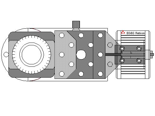
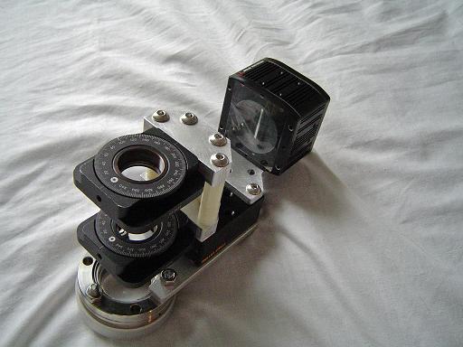
Optics assembly (10/1/2007) Optics assembly for thompson scattering. A high speed line camera is mounted on a linear translation stage. A high energy polarized 532nm laser pulse from a frequency doubled Q switched YAG laser is fired from above the top rotary stage through the beam splitter cube through the plasma focal point. The beam will then exit through an opposing view port, pass through a quarter wave plate and reflect off of a first surface mirror and return through the quarter wave plate thereby shifting the polarization by 90 degrees. The laser pulse then returns through the plasma focus scattering through thompson scattering. The primary beam and scattered photons are reflected off the beam splitter cube toward the high speed line camera. The primary beam is reflected off a deflecting mirror and the scattered light is detected by the camera. |
 |
|
|
|
|
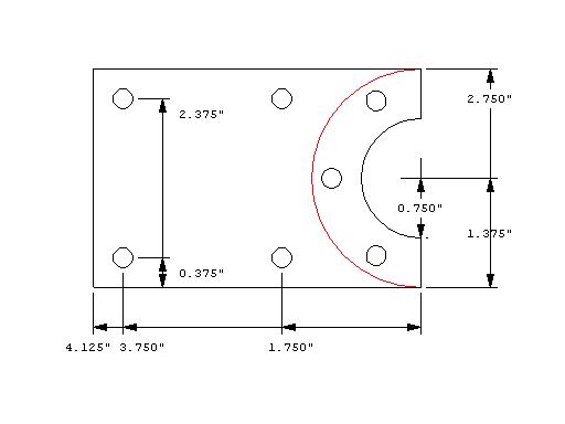 |
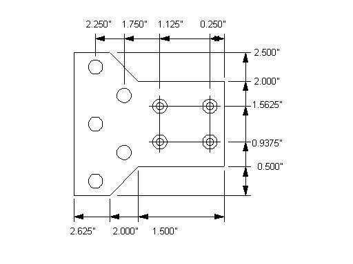
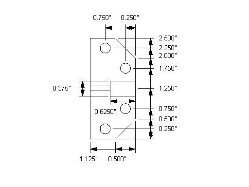
Linear stage mounting plate (10/1/2007) Mounts linear translation stage to 2.75" conflat view port. |
 |
Linear stage mounting plate (10/1/2007) Mounts linear translation stage to 2.75" conflat view port. |
 |
Linear stage (10/1/2007) Linear translation stage adjusts thompson scattering setup to center laser beam on plasma focus. |
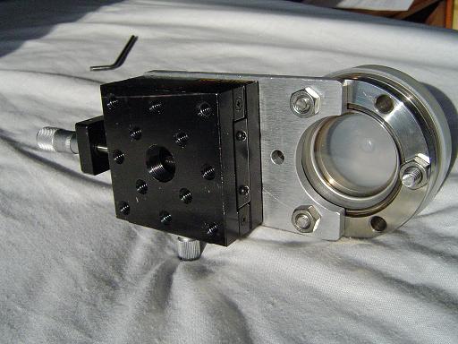 |
Linear stage (10/1/2007) Mounted to view port. |
 |
Reticon camera mount (10/1/2007) Mounts reticon high speed line camera to translation stage. |
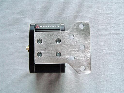 |
Reticon camera mount (10/1/2007) Mounts reticon high speed line camera to translation stage. |
 |
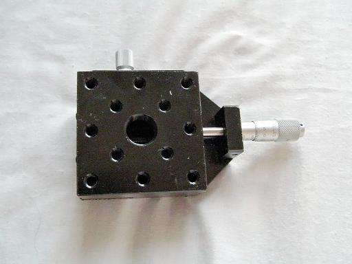
Reticon camera mounted (10/1/2007) Camera mounted to translation stage. |
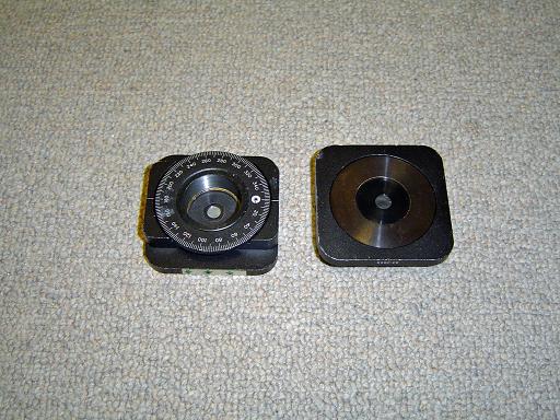 |
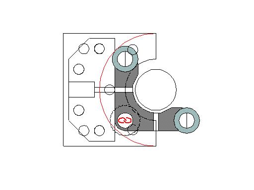
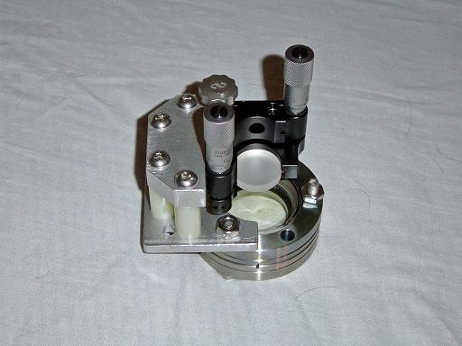
Rotary stages (10/1/2007) Holds polarizer and beam splitter cube. |
 |
Rotary stage mounting plate (10/1/2007) Mounts rotation stage to translation stage. |
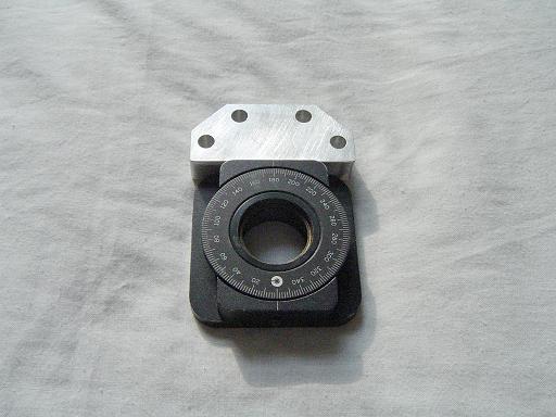 |
Rotary stage mounting plate (10/1/2007) Mounts rotation stage to translation stage. |
 |
Rotary stage mounted (10/1/2007) Rotary stages mounted to translation stage. |
 |
Beam splitter cube (10/1/2007) Polarizing beam splitter cube reflects one polarization at a right angle while transmitting another polarization. |
 |
Reflector mirror (10/1/2007) Reflects probe beam back through the plasma focus. |
 |
Reflector mirror mounting plate (10/1/2007) Mounts reflector mirror to 2.75" conflat view port. |
 |
Reflector mirror mounting plate (10/1/2007) Mounts reflector mirror to 2.75" conflat view port. |
 |
Reflector parts (10/10/2007) Mounts reflector mirror to 2.75" conflat view port. |
 |
Reflector assembly (10/10/2007) Positions first surface mirror over view port. |
 |
He Ne laser (10/1/2007) Helium neon laser will be used for alignment of the YAG laser. |
 |
He Ne laser mount (10/1/2007) Mounts He Ne laser to reactor frame. |
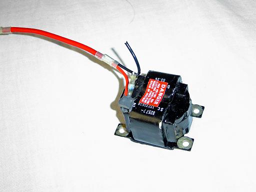
| Trigger transformer (10/1/2007) Provides HV pulse to trigger the flash lamp in YAG laser. |
|
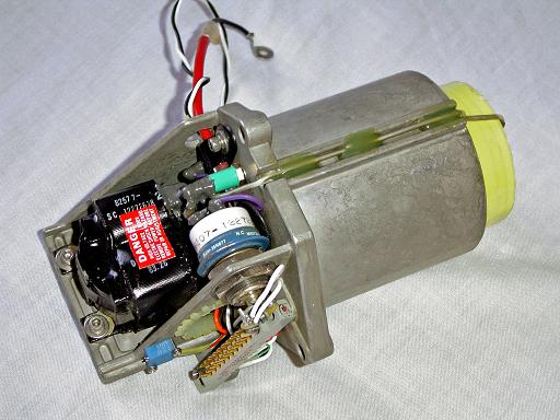 |
Laser PFN (10/1/2007) Pulse forming network for laser flash lamp. |
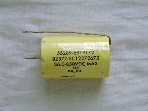 |
PFN capacitor (10/1/2007) Capacitor removed from PFN to be mounted in laser control box. |
 |
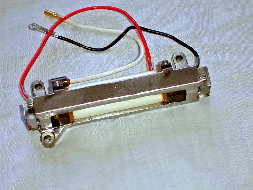
PFN inductor (10/10/2007) Inductor removed from PFN to be mounted in laser control box. |
 |
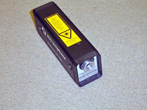
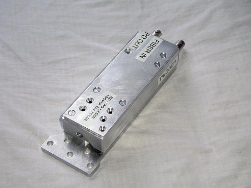
YAG laser (10/1/2007) Q switched YAG laser produces high energy pulse. Q switch in an internal saturatable dye cell. Laser produces a 4ns pulse at approximately 10mJ to 50mJ at 1064nm. This will be frequency doubled to 532nm with a KTP crystal. |
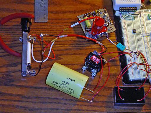 |
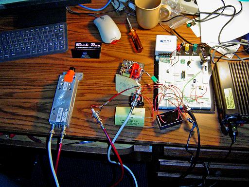
YAG laser test setup (10/10/2007) PFN is connected to EMCO E10 hv power supply, charging capacitor to 800V. Trigger assembly is powered off of PFN capacitor. YAG laser fires through a focusing lens into a sticky note. |
 |
YAG laser test (10/10/2007) YAG laser fires through a sticky note, ejecting plasma from the surface. |
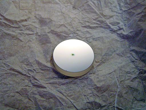 |
YAG laser test (10/10/2007) YAG laser is able to ablate the coating off of a first surface mirror. |
 |
YAG laser mount (10/13/2007) Mounts yag laser to optics platform. |
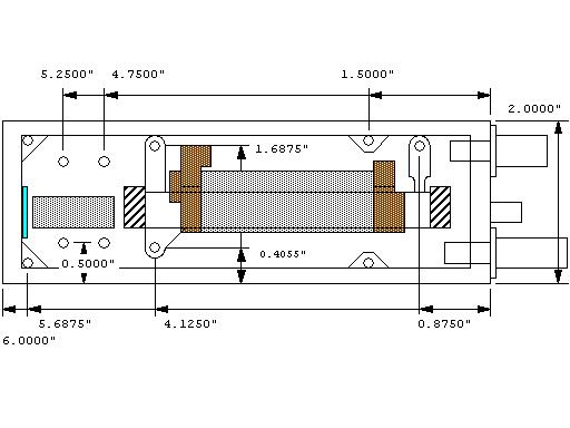 |
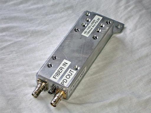
YAG laser case (10/13/2007) Aluminum enclosure for yag laser. |
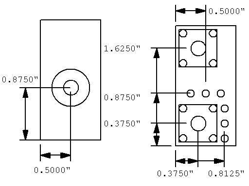 |
YAG laser case (10/13/2007) Ends of case.
|
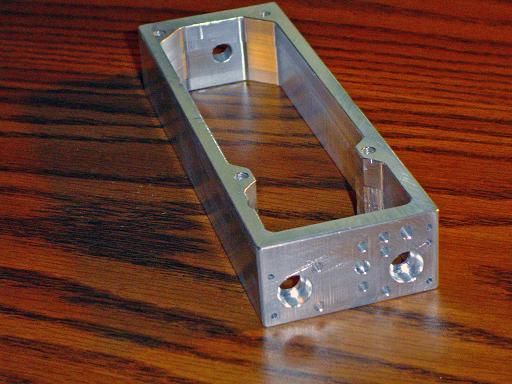 |
YAG laser case (10/13/2007) Aluminum enclosure for yag laser. |
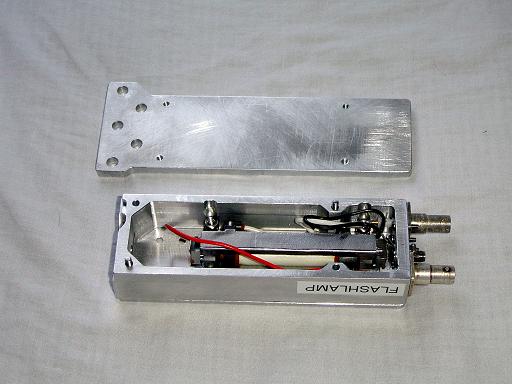 |
YAG laser case (10/13/2007) Yag laser mounted to top cover and enclosed in case. |
 |
YAG laser case (10/13/2007) Yag laser assembled. |
 |
YAG laser case (10/13/2007) Yag laser assembled. |
 |
YAG laser test 2 (10/13/2007) Yag laser test with laser in case. |
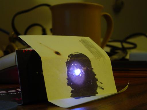 |
YAG laser test2 (10/13/2007) Yag laser focused on sticky note. |
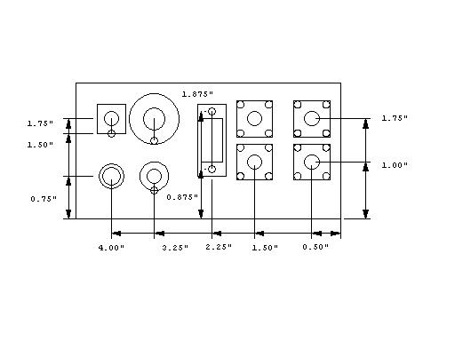 |
YAG PFN box front panel (10/28/2007) Control box front panel. |
 |
YAG PFN box bottom (10/28/2007) |
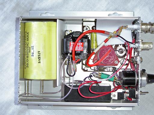 |
YAG PFN box front panel (10/28/2007) Control box contains an HV supply and PFN for the YAG laser. |
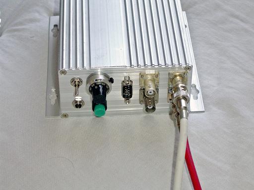 |
YAG PFN box (10/28/2007) Control box complete. DB-9 port will allow future addition of internal PIC micro controller. |
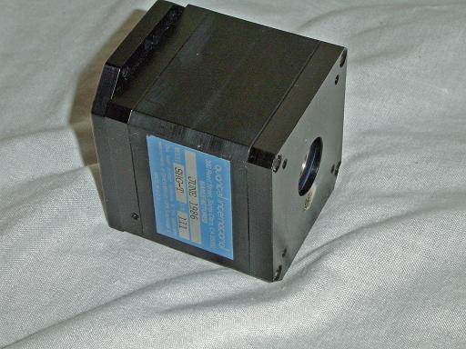 |
Second harmonic generator (10/28/2007) Second harmonic generator frequency doubles 1064nm YAG laser to 532nm output. Reticon camera system is more sensitive at 532nm. Generator is a Quantel SHG-T. |
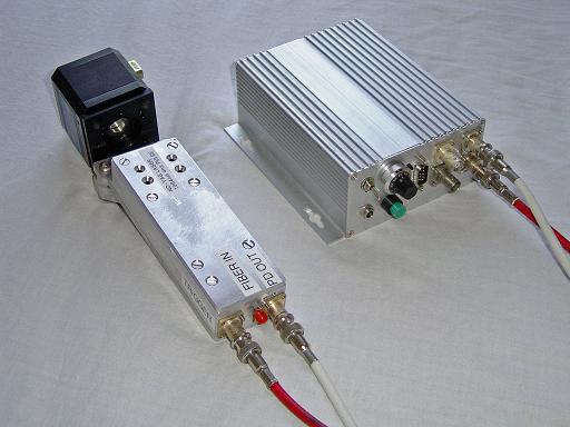 |
SHG / YAG test (10/28/2007) SHG unit mounted on output of YAG laser. |
 |
SHG / YAG test (10/28/2007) Almost parallel to output beam. |
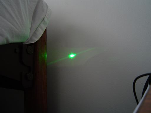 |
SHG / YAG test (10/28/2007) Beam hitting wall. |
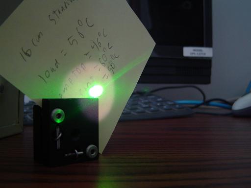 |
SHG / YAG test (10/28/2007) Beam hitting sticky note. |
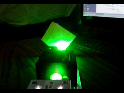 |
SHG / YAG test (10/28/2007) Beam hitting sticky note in dark. |
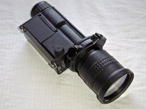 |
Night vision scope (1/09/2008) Gen 1 night vision scope will be used as an image intensifier system to amplify scattered light from plasma. |
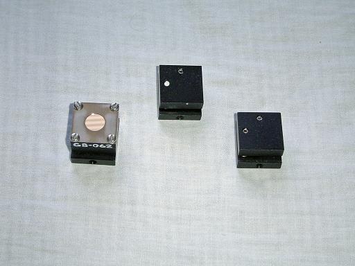 |
Small optics mounts (1/09/2008) Small mounts will be used to position diffraction grating. |
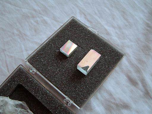 |
Diffraction gratings (1/09/2008) Diffraction gratings will be used to separate out different spectral components of the thompson scattered light from the plasma. |
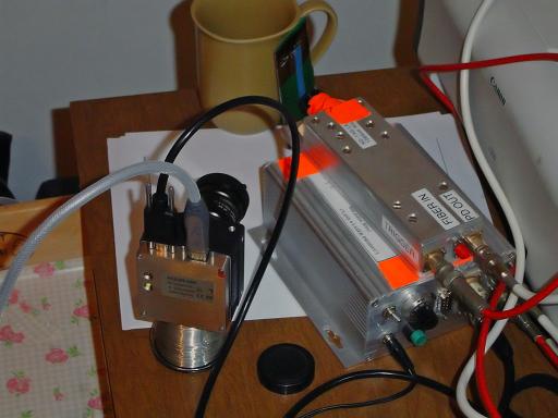 |
Basler Camera (7/26/2008) Basler A301F firewire camera with external trigger will be used to detect thompson scattering from the plasma. Camera will image the output of the image intensifier tube which will amplify the laser beam scattered by the plasma. Camera will be externally triggered and synchronized with the Nd:YAG laser. Camera trigger is tested by focusing YAG laser onto a paper target and imaging the plasma plume generated. |
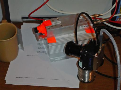 |
Basler Camera (7/26/2008)
|
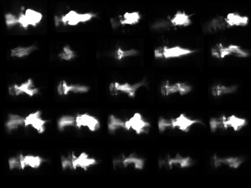 |
Plasma Images (7/26/2008) Plasma generated by laser ablation of the surface. Since the camera images the paper nearly edge on, the surface acts as a mirror due to the nearly tangental angle of incidence of the light generated by the plasma as seen as the symmetrical reflection in some of the images. Compare to the above color image of the plasma and note the improved detail and contrast. |
|
|
|
|
|
|
| Useful links: http://www.fusor.net/ Open Source Fusion Research Consortium. |
|
By attempting to reproduce any experiments or devices listed on this domain in part or in whole, you agree to hold me harmless against any lawsuit or liability. Copyright © 1998 - 2005 by Andrew Seltzman. All rights reserved. |
|
| Contact me at: admin@rtftechnologies.org | |