| IEC Fusion Reactor Mark 3 Hemisphere |
 |
 |
 |
 |
 |
 |
 |
|
|
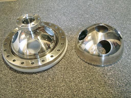
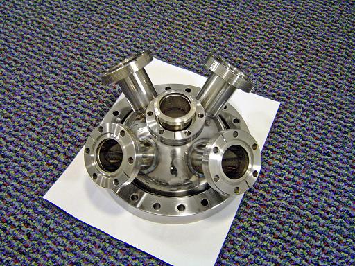
Overview: Fusion reaction rates are negatively affected by impurities within the plasma, requiring a tight vacuum system to prevent atmospheric leaks and allow a lower operational pressure. A lower operational pressure will allow higher voltages to be present on inner grid with out it melting due to over ionization of gas prevent within the vacuum chamber. This higher voltage will allow greater collision energy between deuterium ions, increasing the cross section and yielding a higher neutron output. The mark 3 reactor vacuum chamber will be constructed from two 6" 304 stainless steel hemispheres joined with 8" conflat flanges. The two on axis ports will be used for a HV feed through and vacuum pump connection, while the 8 off axis ports mounted at 45 degrees will accommodate ion injectors and instrumentation.
|
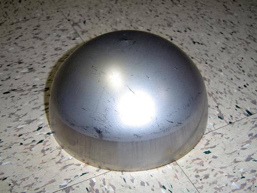 |
Hemisphere (2/3/2006) |
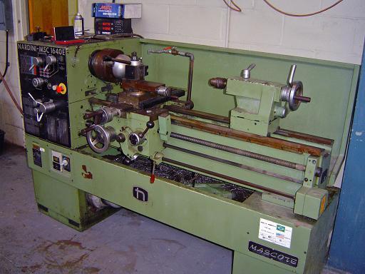 |
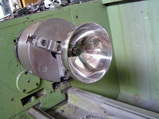
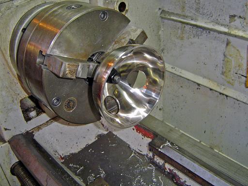
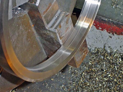
Hemisphere Polishing (6/10/2006) Hemisphere is held in OD jaws on a lathe. |
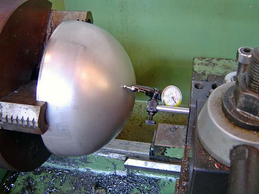 |
Hemisphere Polishing (6/10/2006) Hemisphere is checked with a dial indicator to verify centering on chuck and spherical nature. Total deviation does not exceed 0.01" |
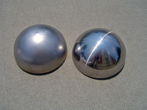 |
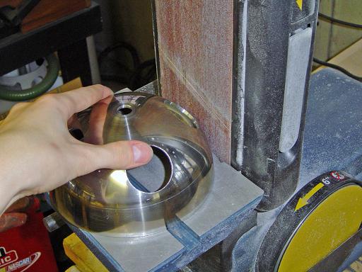
Hemisphere Polishing (6/10/2006) Unpolished and polished hemispheres. |
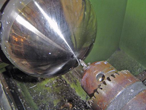 |
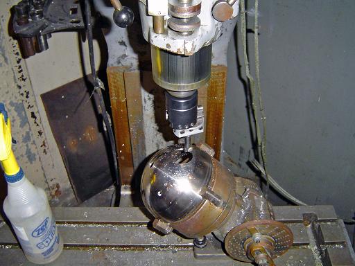
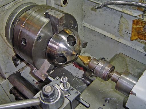
Center drill (8/12/2006) Hemisphere is center drilled. |
 |
Center drill (8/12/2006) Center drill size is incrementally increased to 5/16". |
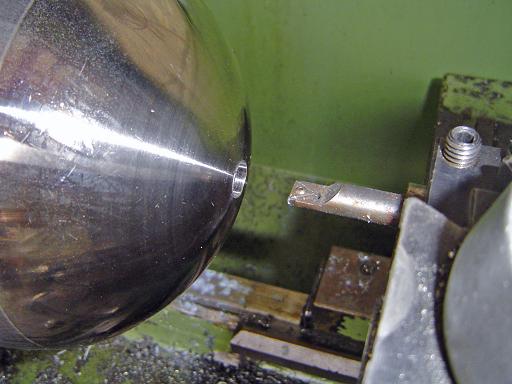 |
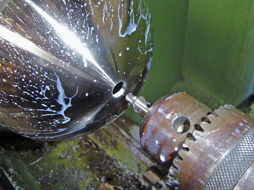
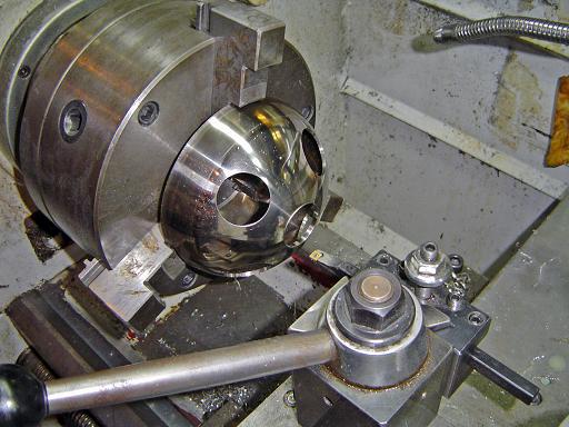
Center bore (8/12/2006) Hole is bored out to fit a 1/2" threaded rod. |
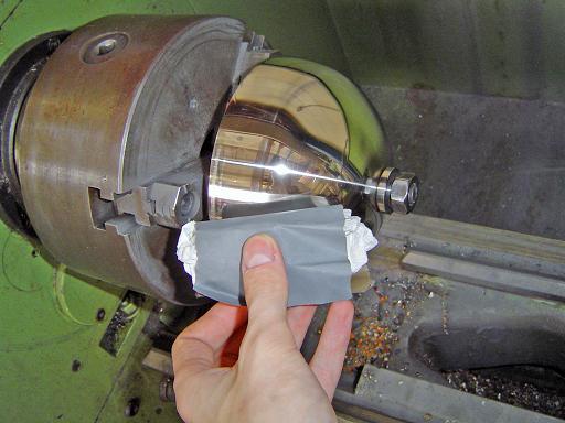 |
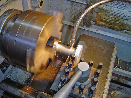
Hemisphere Polishing (12/21/2006) Hemisphere is mounted on threaded rod and polished to 2500 grit. |
 |
Hemisphere Polishing (12/21/2006)
|
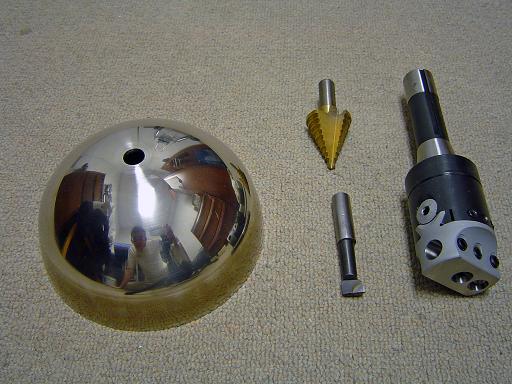 |
Hemisphere and tooling (3/17/2007) Hemisphere polished with up to 2500 grit and shown with tooling to bore the 45 degree holes for the ion injector ports. While held in the indexing head the step drill will be used to drill a 1.375" hole in the hemisphere. The boring head will subsequently be used to increase the hole diameter to several thousandths below 1.5" for a snug fit for the conflat weld stubs. Boring method has been successfully tested of a scrap piece of 1/8" steel. |
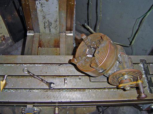 |
Indexing head (3/18/2007) An indexing head will be used in conjunction with center drills and a boring head to bore the 4 non-axial vacuum ports. Indexing head is set at 45 degrees. |
 |
Centering hemisphere in chuck (3/18/2007) Hemisphere is centered by measuring distance on each of the 4 chuck jaws to the body of the chuck. |
 |
Measuring hemisphere (3/18/2007) Edges of the hemisphere measure 6.026" in diameter. |
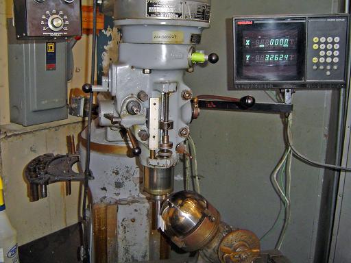 |
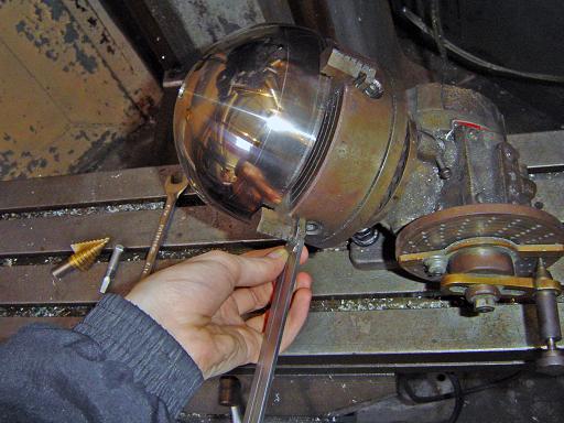
Centering hemisphere on table (3/18/2007) A precision 0.5" rod is used to zero the hemisphere in the translation axis by iteratively measuring from the contact points on the edge and surface 90 degrees of arc apart. |
 |
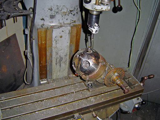
Center drilling hemisphere (3/18/2007) Hemisphere is center drilled at 90 degree increments. |
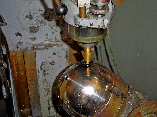 |
Step drilling hemisphere (3/18/2007) Hemisphere is step drilled to 1.375" ID. |
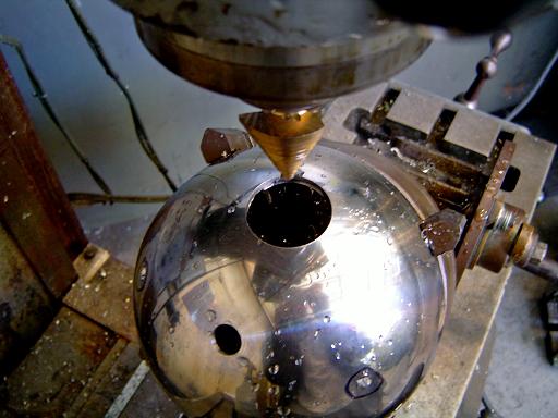 |
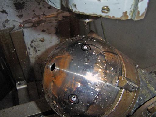
Step drilling hemisphere (3/18/2007) Step drilling complete. |
 |
Boring hemisphere (3/18/2007) A boring head is used to increase the hole diameter to 1.495" ID. |
 |
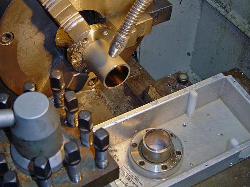
Port check (3/18/2007) Conflat half nipple fits snugly in the bored hole. |
 |
Hemisphere bored (3/18/2007) The previous procedure is repeated on the remaining 3 holes. |
 |
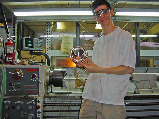
Hemisphere bored (3/18/2007) Me holding hemisphere. |
 |
Conflat nipples (3/17/2007) 2.75" conflat nipples (4" long) will be cut on a lathe providing 8 non-rotatable 2.5" long half nipples (4 per hemisphere) for the ion injector ports, and 2 rotatable 1.5" long half nipples for the on axis ports for vacuum and grid feed through. |
 |
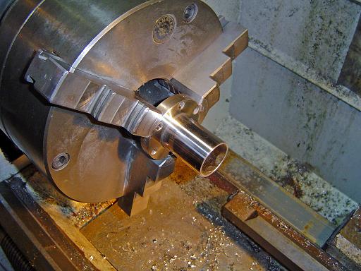
Cutting nipple (3/18/2007) Nipple is cut on a lathe to provide 2.5" long non-rotatable half nipples. |
 |
Nipple cut (3/18/2007) Rotatable section is cut off. The rotatable sections will be used for the on axis ports. |
 |
Nipple polished (3/18/2007) Half nipple is polished on the lathe with 600 grit sandpaper. |
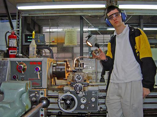 |
Nipple cutoff (3/18/2007) Me and cutoff rotatable section. |
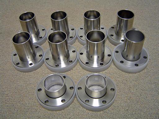 |
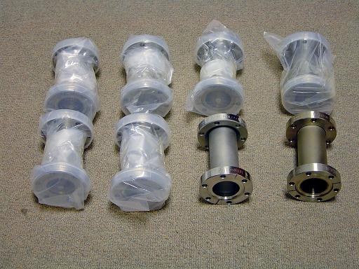
Reactor ports (3/20/2007) 8 non-rotatable half nipples for ion injectors and instrumentation and 2 rotatable short half nipples for vacuum and grid feed through. |
 |
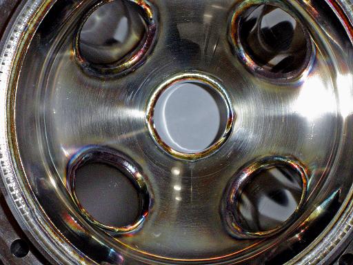
Hemisphere bored (3/20/2007) Close up of bored hemisphere. |
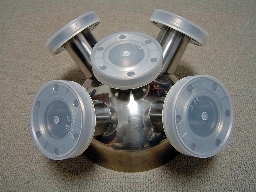 |
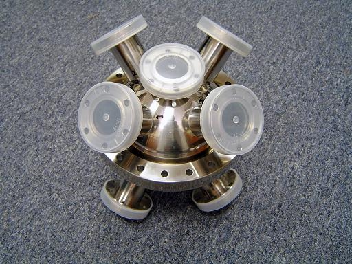
Hemisphere port test (3/20/2007) Conflat ports placed in approximate position for clearance testing. |
 |
Hemisphere base sanding (5/24/2007) Hemisphere base is sanded, removing 0.045" to allow the base of the hemisphere to be welded level to the lip of the conflat flange weld ring. |
 |
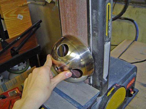
Hemisphere side sanding (5/24/2007) Hemisphere side is sanded to allow a snug fit in the the conflat weld ring. |
 |
Hemisphere side polishing (5/24/2007) Hemisphere side area that was sanded on the belt sander is then polished to 600 grit. |
 |
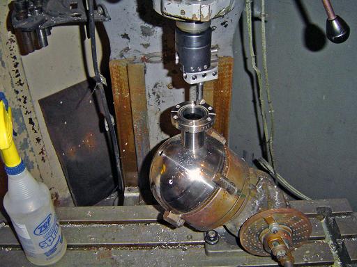
Axis port step drilling(5/24/2007) A step drill is used to take the on axis port hole to 1.375" |
 |
Axis port step boring(5/24/2007) A boring bar is then used to increase the hole diameter to 1.495". |
 |
Axis port test fit(5/24/2007) The on axis port is test fitted in the bored hole. |
 |
Axis port (5/24/2007) Me and completed hemisphere. |
 |
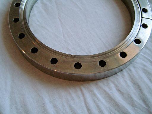
Conflat weld ring boring(5/24/2007) The weld lip on the 8" rotatable conflat flange weld ring is then bored out to allow clearance for the hemisphere to be inserted from the knife edge side. |
 |
Weld ring test fit(5/24/2007) Hemisphere fits snugly into rotatable conflat ring. Lip of hemisphere is flush with the lip of the weld ring. |
 |
Weld relief groove (11/20/2007) Machined into weld ring surface to enable better weld. |
 |
Completed hemispheres(5/24/2007) The procedure is repeated on the second hemisphere. |
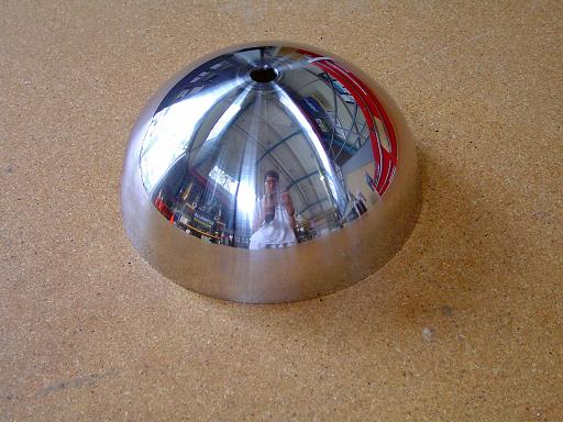 |
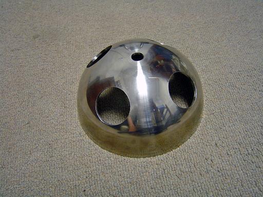
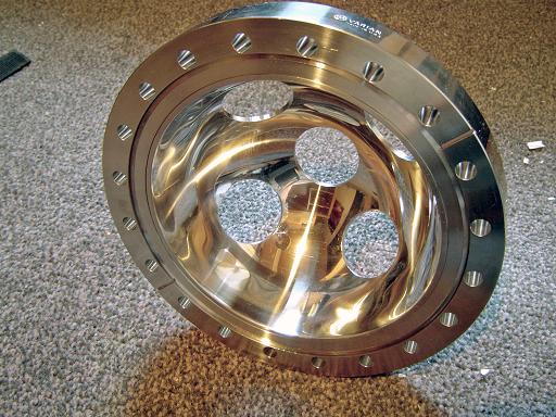
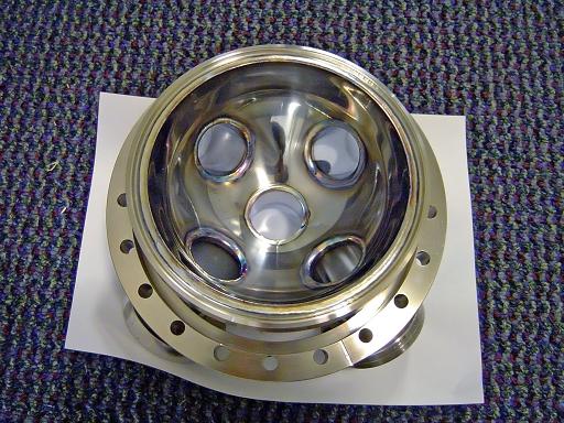
Third Hemisphere Polished (06/05/2007) Third hemisphere polished with reflection of machine shop. Third hemisphere was machined t replace first hemisphere that has slightly oversized ports on the 45 degree angles and a lower quality polish. |
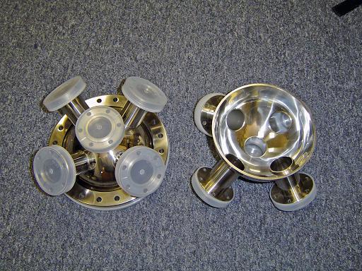 |
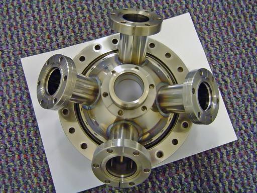
Port Test Fit (06/07/2007) Weld stubs are test fitted into hemispheres. All ports fit snugly. |
 |
Port Test Fit (06/07/2007) Hemispheres aligned with each other. |
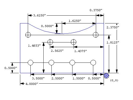 |
Core Mounting Plate (3/4/2006) Mounting plate to attach an 8" conflat to an 8020 frame. |
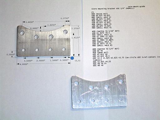 |
Core Mounting Plate (3/6/2006) Plate is milled on a CNC mill. Curve is milled into plate to accommodate the curvature of the hemisphere. |
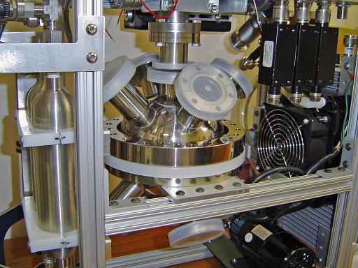 |
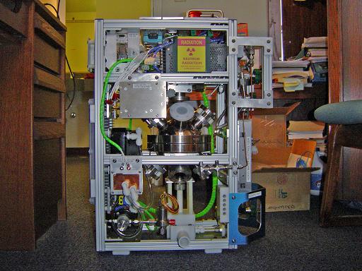
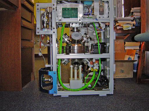
Reactor frame test fit (06/07/2007) Reactor core (not yet welded) is fit into reactor frame. |
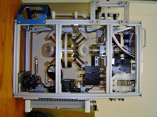 |
Reactor frame test fit (06/07/2007) Full view of reactor frame with un-welded core. |
 |
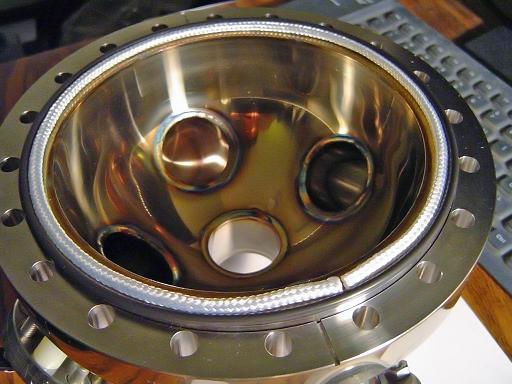
Hemisphere welded (01/05/2008) Hemisphere welding complete. |
 |
Hemisphere welded (01/05/2008) Ports welded to hemisphere |
 |
Hemisphere welded (01/05/2008) Hemisphere welded to 8" rotatable conflat flange. |
 |
Hemisphere welded (01/05/2008) Interior welds. |
 |
Grid position (01/05/2008) Cooled grid is positioned at the correct height within the reactor. |
 |
Grid mounted (01/05/2008) Cooled grid mounts to bottom port. |
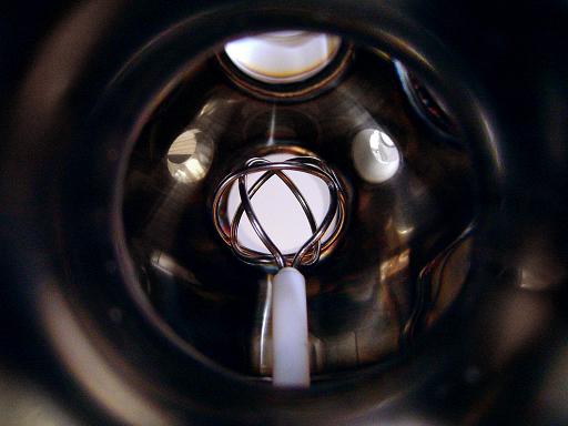 |
Grid mounted (01/05/2008) Alignment looking through an ion injector port. |
 |
Reactor core installed (01/05/2008) Core mounts within reactor. |
 |
Reactor core installed (01/05/2008) Core mounts within reactor. |
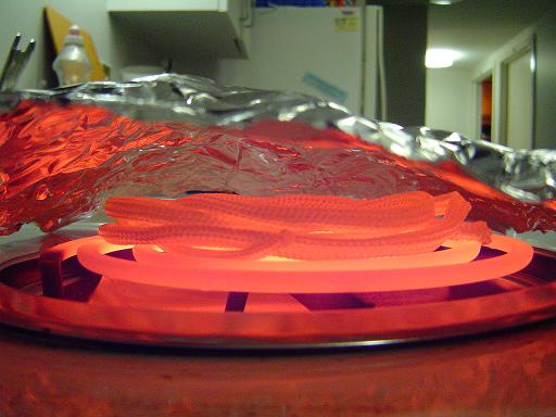 |
Plasma limiter bake out (03/26/2008) Due to plasma bombardment damage to the o-ring and out gassing in preliminary tests an alumina fabric plasma limiter was installed to shield the o-ring. The limiter was baked out at 950F for 60 min to remove any binders added in the manufacturing process. |
 |
Plasma limiter (03/26/2008) Shields o-ring from plasma. |
|
|
|
| Useful links: http://www.fusor.net/ Open Source Fusion Research Consortium. |
|
By attempting to reproduce any experiments or devices listed on this domain in part or in whole, you agree to hold me harmless against any lawsuit or liability. Copyright © 1998 - 2005 by Andrew Seltzman. All rights reserved. |
|
| Contact me at: admin@rtftechnologies.org | |
