IEC Fusion Reactor Mark 3 Grid Cooling System
IEC Fusion Reactor Mark 3 Grid Cooling System |
 |
 |
 |
 |
 |
 |
 |
| Overview:
|
|
 |
|
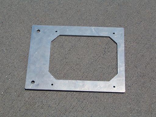 |
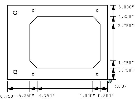
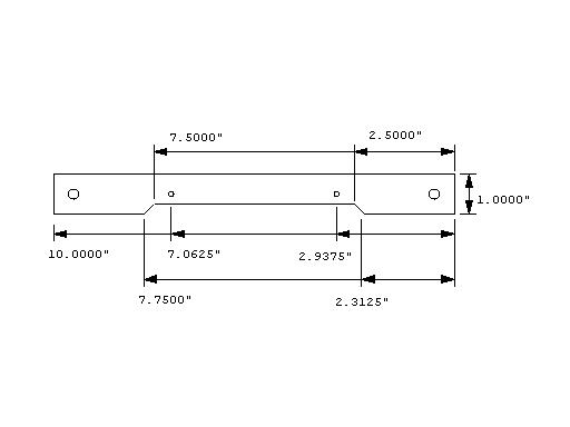
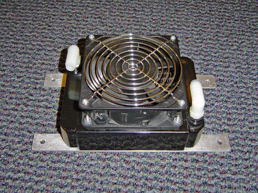
Fan Mount (7/17/2006) Fan mounting plate. |
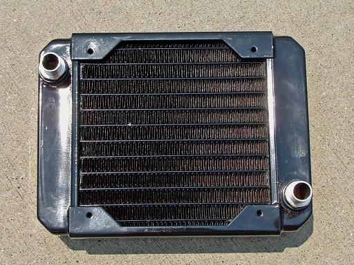 |
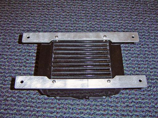
Heat Exchanger (7/17/2006) |
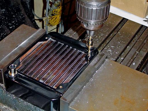 |
Heat Exchanger (7/17/2006) Drilling hole for 6-32 screws. |
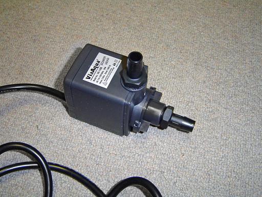 |
Water Pump (9/30/2006) Pump Circulates water through the primary cooling system. |
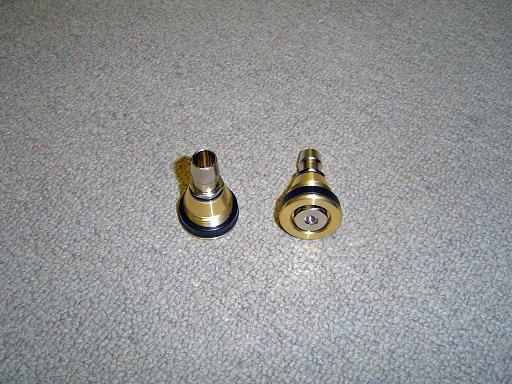 |
Water Fill / Drain Ports (9/30/2006) Ports for filling and draining water from the cooling system. |
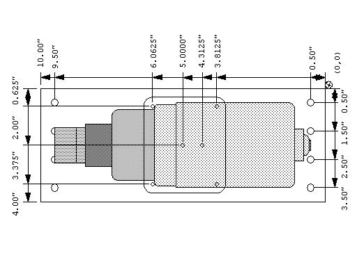 |
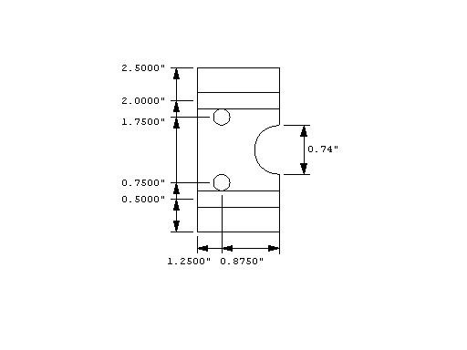
Micropump Mount (10/14/2006) |
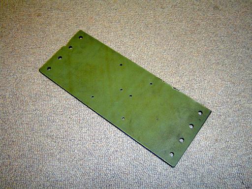 |
Micropump Mount (10/14/2006) Mounting plate is milled from kevlar coated carbon fiber plate. |
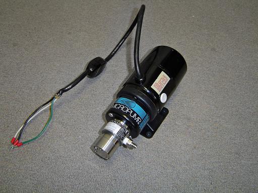 |
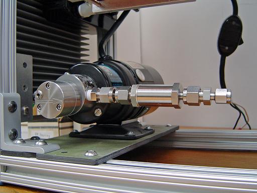
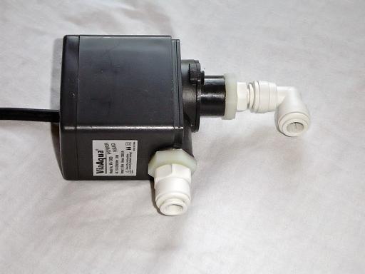
Micropump (10/14/2006) Magnetically coupled micropump will be used to pump fluorinert coolant through the grid coolant loop. The pump can deliver 0.87gpm at 80psi. |
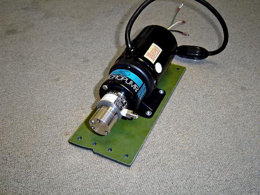 |
Micropump Mounted (10/14/2006) Micropump mounts on carbon fiber plate. |
 |
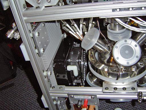
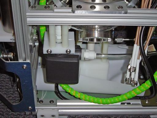
Micropump Mounted on Frame (10/14/2006) Micropump mounting plate mounts to reactor frame on mounting plate. |
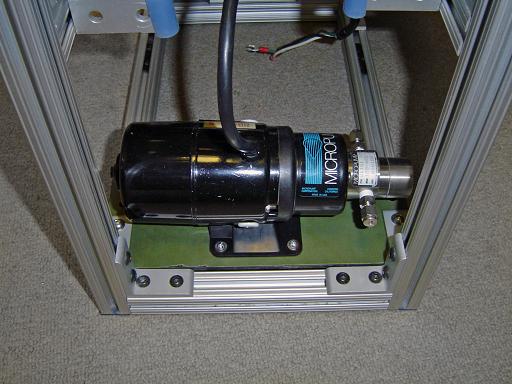 |
Micropump Mounted on Frame (10/14/2006)
|
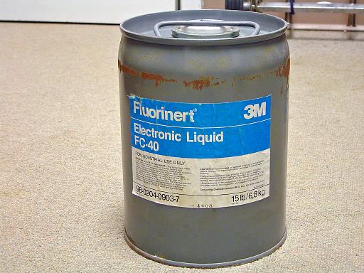 |
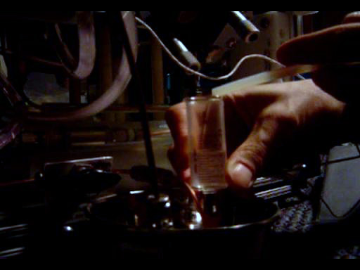
Fluorinert (10/14/2006) Fluorinert FC-40 coolant will be pumped through the central grid cooling it and preventing thermionic emission at high ion bombardment levels. |
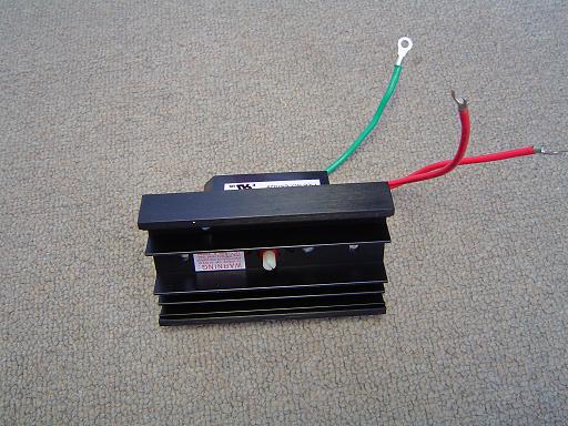 |
Micropump motor speed control (11/5/2006) Dimmer control is used to vary the speed and therefore pressure of the fluorinert in the grid cooling loop. |
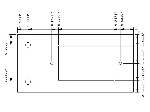 |
Speed control mounting plate(12/17/2006) Mounts micropump speed control to reactor frame. |
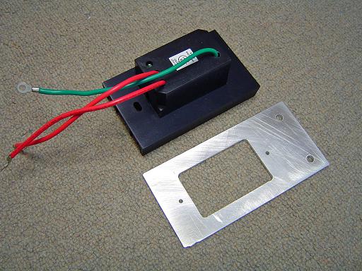 |
Speed control mounting plate(12/17/2006)
|
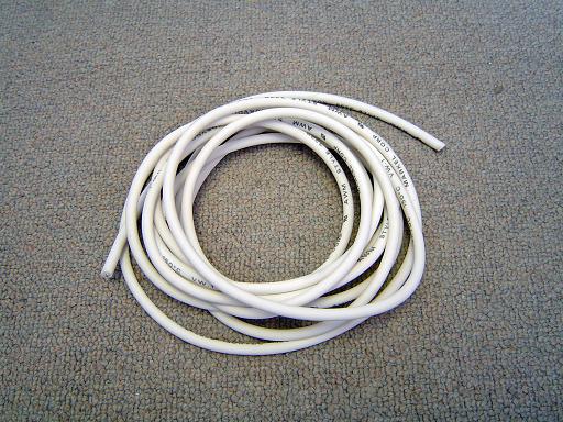 |
HV wire (11/5/2006) 40kV rated HV wire for power hookup. OD is 1/4" |
 |
HV wire and teflon tube (11/5/2006) 1/4" OD wire fits through 1/4" ID 3/8" OD teflon tube for greater insulation. |
 |
Cooled Grid (3/22/2007): Cooled grid is constructed. |
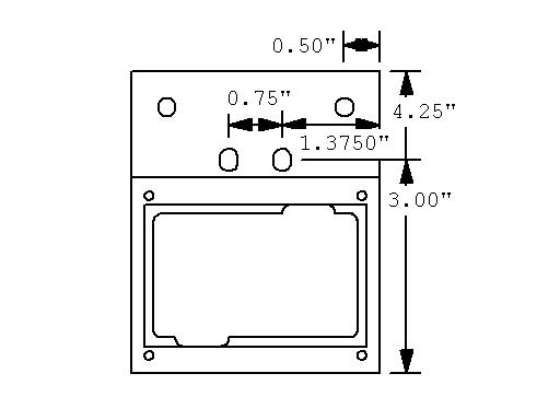 |
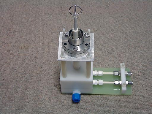
Fluorinert chiller mount (3/22/2007): |
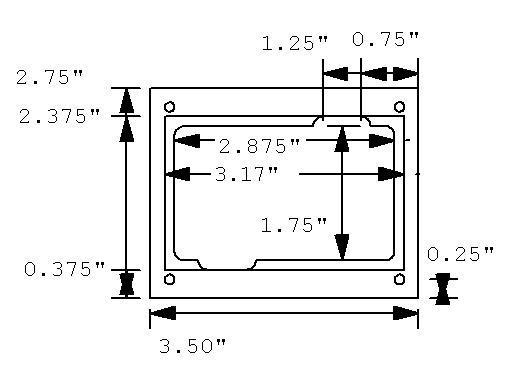 |
Fluorinert chiller compression plate (3/22/2007): |
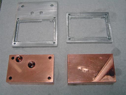 |
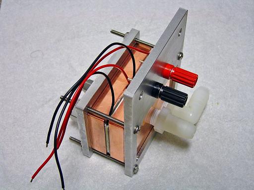
Fluorinert chiller heat exchanger blocks (3/22/2007): Shown with mount and compression plate. |
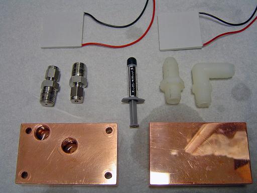 |
Fluorinert chiller heat exchanger blocks (3/22/2007): Shown with thermoelectric coolers (100W each) model CP1-12710 as well as swagelok fittings for fluorinert and plastic fittings for water. |
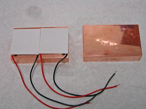 |
Thermoelectric coolers (3/22/2007): In position on heat exchanger blocks. |
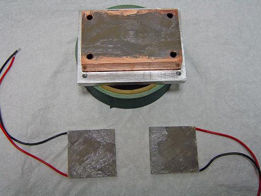 |
Thermoelectric coolers (3/22/2007): Coated with arctic silver 5. |
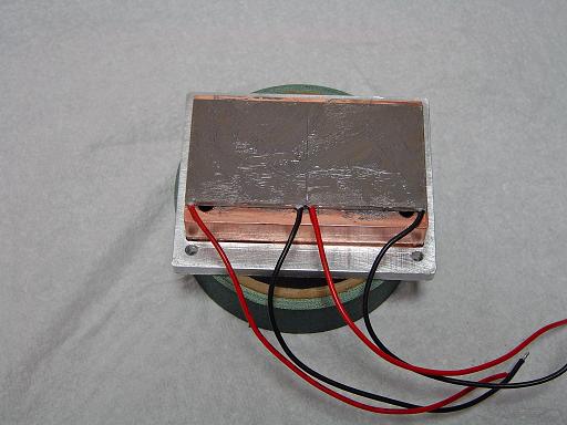 |
Thermoelectric coolers mounted (3/22/2007):
|
 |
Fluorinert chiller (3/22/2007): Bolts together with compression plate. Water side shown. |
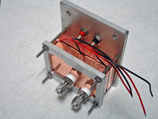 |
Fluorinert chiller (3/22/2007): Fluorinert side shown. |
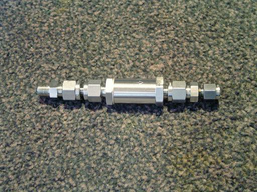 |
Fluorinert filter (5/24/2007): 60 micron swagelok filter is placed in the coolant line feeding the grid to prevent particulate matter that may be introduced when filling the cooling system from clogging the cooling tube. |
 |
Filter mounted (5/24/2007): Filter mounts directly to the outlet of the micropump. |
 |
Heat exchanger mount (10/28/2007): Mounts heat exchanger to reactor frame. |
 |
Heat exchanger mount (10/28/2007): Attached to heat exchanger. |
 |
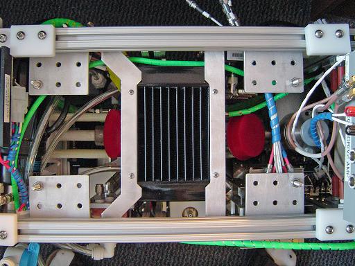
Heat exchanger (10/28/2007): Assembled system. |
 |
Heat exchanger (10/28/2007): Mounted to reactor frame. Exhaust from heat exchanger flows over amplifier heat sink, cooling it as well. |
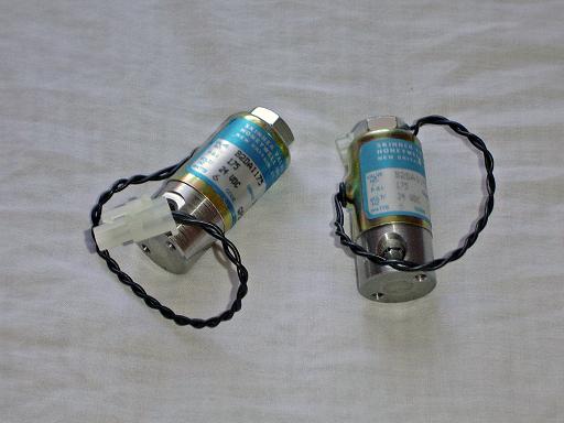 |
Solenoid valve (11/20/2007): Isolates grid from cooling system. |
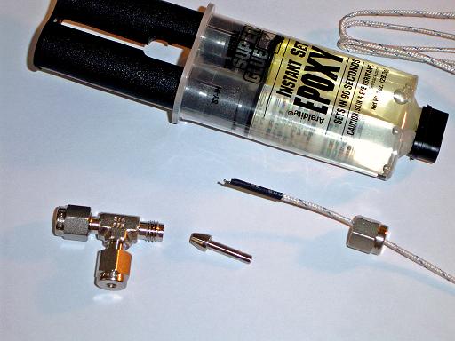 |
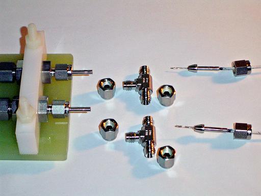
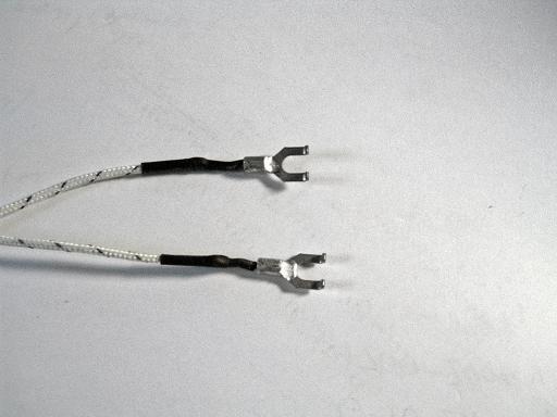
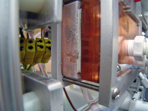
Coolant monitoring thermocouple parts (12/3/2007): Thermocouples will monitor coolant feed and return temperatures. |
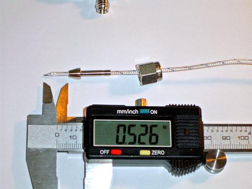 |
Coolant monitoring thermocouple position (12/3/2007): Thermocouples is pulled through 1/8" swagelok port connector and marked with sharpie for final positioning. |
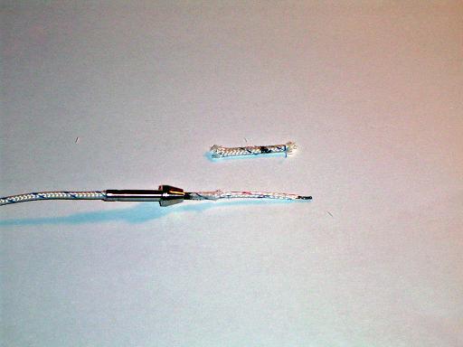 |
Coolant monitoring thermocouple insulation (12/3/2007): Outer insulation is stripped off (shown), followed by inner insulation. |
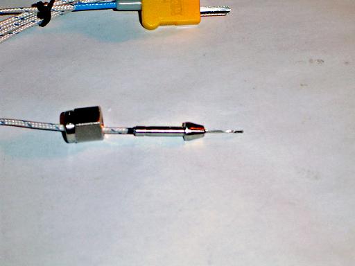 |
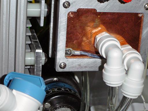
Coolant monitoring thermocouple epoxied (12/3/2007): Thermocouples is epoxied into port connector. Epoxy extends about 3/8" into connector, thermocouple wires do not touch metal wall. |
 |
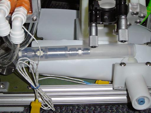
Coolant monitoring thermocouple (12/3/2007): The junction is positioned at the center of the swagelok tee, in the coolant flow. |
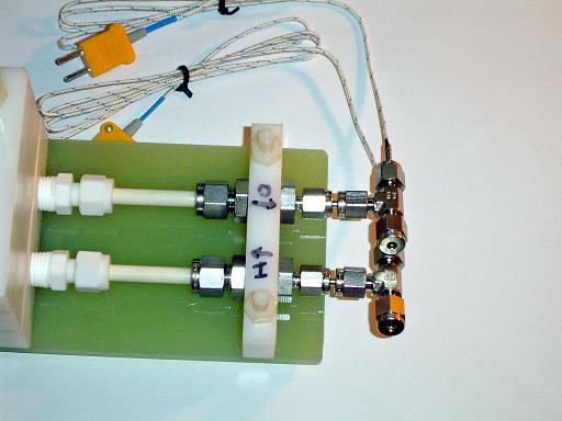 |
Coolant monitoring thermocouple (12/3/2007): Thermocouples connect to cooled grid system. Knowing the specific heat of the coolant, the flow rate and the feed and return temperatures, the total heat deposited into the grid may be calculated. |
 |
Micropump speed control connections (1/05/2008) Speed control is connected to micropump. |
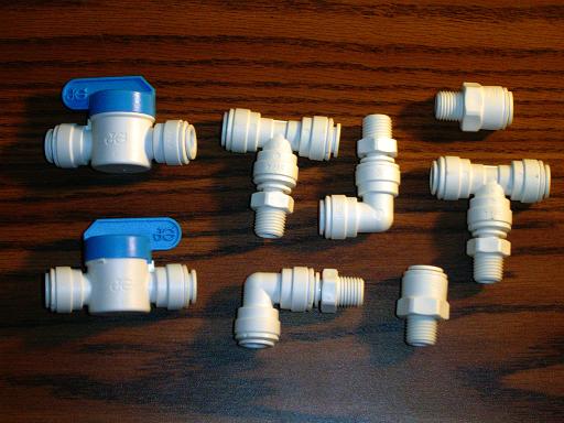 |
Cooling fittings (1/20/2008) 3/8" tube push to connect fittings for primary cooling loop. |
 |
Water pump mount (1/20/2008) Mounts water pump to reactor frame. |
 |
Water pump fittings (1/20/2008) Push to connect fittings on water pump. |
 |
Water pump mounted (1/20/2008) Water pump mounted on reactor frame, positioned lower then radiator for proper operation. |
 |
Cooling system hookup (1/20/2008) Primary / secondary cooling loop heat exchanger connected to cooling system. Also visible are the fill and drain valves. |
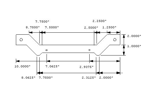 |
Offset heat exchanger mount (2/06/2008) New mount allows heat exchanger to be raised by 1" on the frame, providing better clearance for the lower ion injector port. |
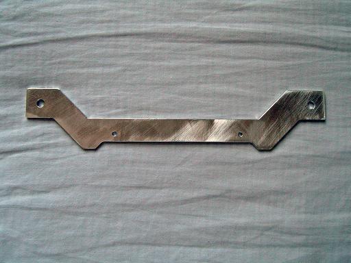 |
Offset heat exchanger mount (2/06/2008)
|
 |
Offset heat exchanger mount (2/06/2008) Replaces old mount. |
 |
Screw mount thermocouple (2/06/2008) Attaches via 6-32 screw. |
 |
Fluorinert chiller thermocouple (2/06/2008) Thermocouple attaches to hot side of chiller. |
 |
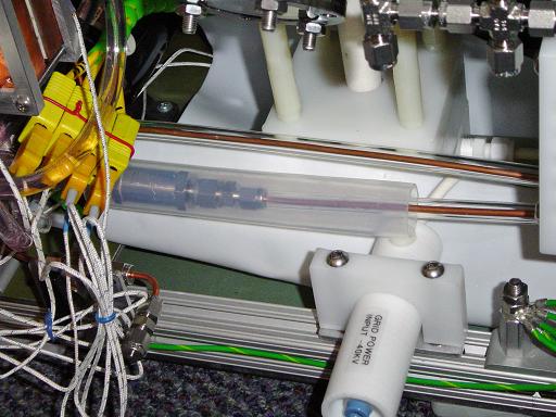
Filter insulator (2/06/2008) Teflon tube insulates filter assembly from high voltage components. |
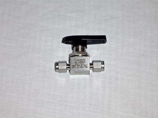 |
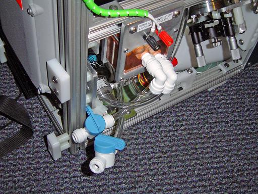
Fluorinert valve (2/06/2008) Swagelok valves for fluorinert fill and drain. |
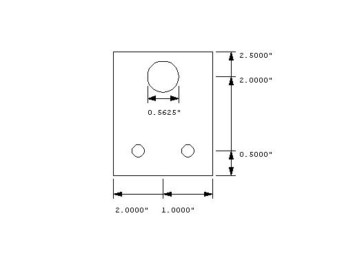 |
Fluorinert valve mount (2/06/2008) Mount for swagelok valve. |
 |
Fluorinert valve mount (2/06/2008) Mount for swagelok valve. |
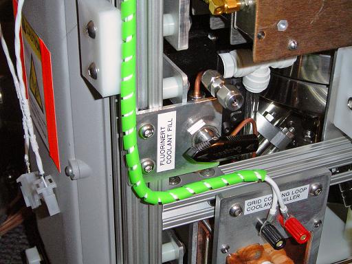 |
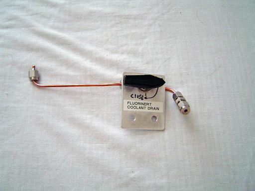
Fluorinert fill valve mounted (2/06/2008) Valve mounts on reactor frame. |
Pressure transducer (2/14/2008) 100 psi pressure transducer generates 1-6vdc output for 0-100psi. Transducer measures pressure to grid assembly. |
|
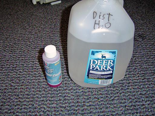 |
Distilled water (2/19/2008) Distilled water and Zerex corrosion inhibitors added to primary cooling loop. |
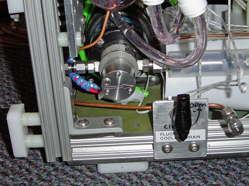 |
Fluorinert drain valve mounted (2/19/2008) Valve mounts on reactor frame. |
 |
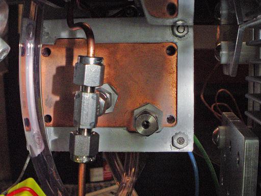
Fluorinert feed and return lines (2/19/2008) Grid cooling system is connected to grid. |
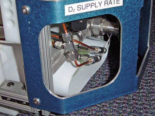 |
Grid connections (2/19/2008) Cooling system connects to grid. |
Pressure transducer (2/19/2008) Pressure transducer mounted on reactor frame. |
|
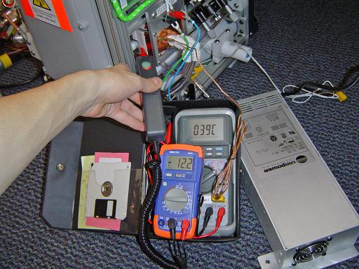 |
Fluorinert chiller test (2/19/2008) Chiller is run at 24V (two 12v TECs in series) with no load on the fluorinert loop. Cold side is -12C, hot side is 39C. |
 |
Fluorinert chiller test (2/19/2008) Ice forms in cold side of chiller. |
 |
Fluorinert chiller test (2/19/2008) Ice forms in cold side of chiller. Also shown is tee connecting chiller to fill valve and return line. |
 |
Micropump connections (2/19/2008) Micropump connects to chiller and drain valve. Pump is set to run at 60 psi. |
 |
Flow Test (2/19/2008) At 80psi the flow rate through the grid was 1ml/s. |
 |
Grid connections (2/19/2008) Viewed from bottom. |
 |
Thermocouple connections (2/19/2008) Thermocouples connect to control system. |
 |
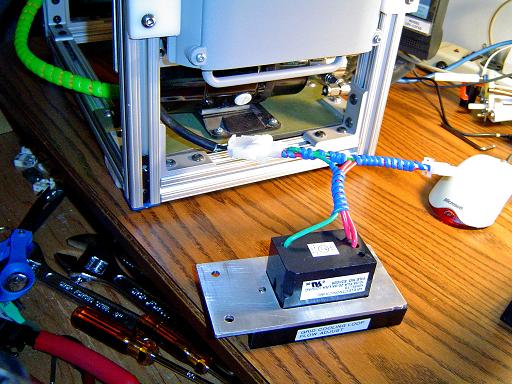
Chiller power supply (2/19/2008) Dedicated 12V power supply for chiller. Running at 24V was found to overload the primary cooing loop, leading to reduced cooling efficiency and excessive condensation. System was switched to 12V. |
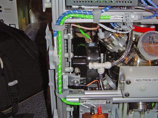 |
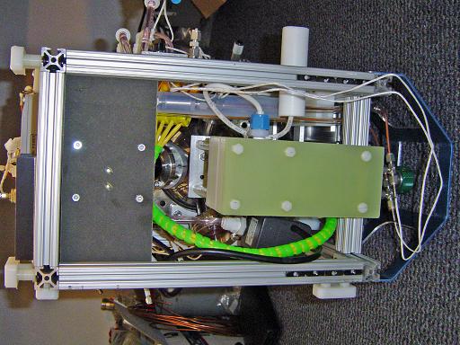
Cable routing (2/19/2008) Cables are velcro tied to the reactor frame. |
|
|
|
|
|
|
|
|
|
|
|
|
| Useful links:http://www.fusor.net/ Open Source Fusion Research Consortium. | |
By attempting to reproduce any experiments or devices listed on this domain in part or in whole, you agree to hold me harmless against any lawsuit or liability. Copyright © 1998 - 2005 by Andrew Seltzman. All rights reserved. |
|
| Contact me at: admin@rtftechnologies.org | |