| IEC Fusion Reactor Mark 3 Control System |
 |
 |
 |
 |
 |
 |
 |
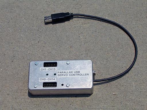
The Mark 3 control system will allow reactor control and sensor feedback over a single USB 2.0 connection to a computer. The control system will be software based for remote operation and will be implemented in LabView. The control computer connects to the reactor through a single USB port. The front panel USB port is connected to an internal multi port hub that links multiple internal sensor and control interfaces to a common connection. An internal NI USB-6008 will provide analog output for controlling the main HV power supplies, digital outputs for controlling switching, a counter channel for connecting to the neutron detector pulse output, as well as analog and digital inputs for sensor data. Although the main power supply's will be controlled over the computer interface, due to safety considerations the control system will have manual controls for vacuum pump power and HV power enable. The control computer will be able to monitor pump operation, but power to the vacuum pumps will be under complete manuel control. The control system will be able to control the HV power systems with the analog outputs on the NI USB-6008, however in addition to internal software interlocks, external guarded switches will connect to the power supplies hardware interlock port to prevent accidental activation due to computer errors. Additional USB devices including a web cam for visual operation, a servo controller for valve control, and an additional data logger will connect to the internal hub. The web cam will observe the plasma within the core through a view port, preventing exposure to bremsstrahlung x-rays generated by accelerated electrons colliding with the reactor core walls. The servo controller (Parallax USB servo Controller) can drive up to 16 hobby servos and is used to implement throttle and fuel valve control as part of the automatic reactor pressure stabilization control system that will be implemented in labview. |
|
|
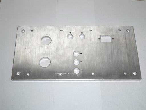
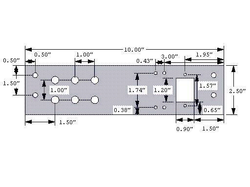
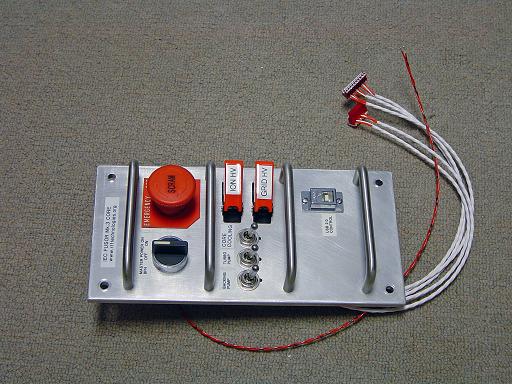
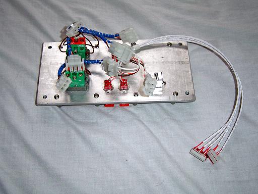
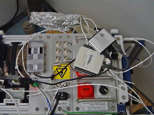
Control Panel The main control panel was fabricated out of 0.25" aluminum and measures 10" by 5". This panel will hold all main power switches and the USB interface port. |
|
|
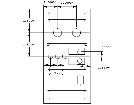
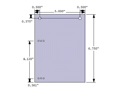
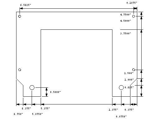
Control Panel CAD Main mounting holes are 1/4" ID and are centered at 0.5" from any side. Rotary and E-Stop switch holed are 0.88" ID. Switch mounting holes are 15/32" and have a 1/8" positioning hole located 0.625" from their center in the OFF direction. Usb connector cutout is centered 2.5" from the bottom plate with the right edge 1" from the right end of the panel. The dimensions are given in this PDF. |
|
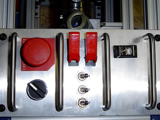
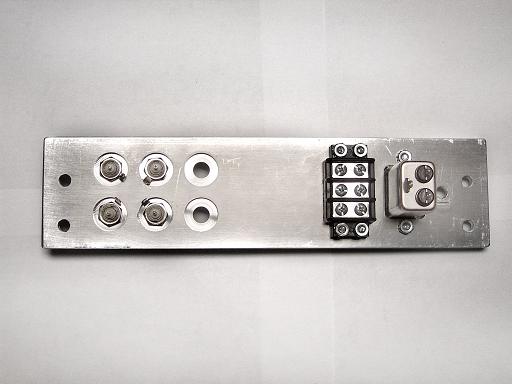
Control Panel Switches Switches are installed into milled holes and switch guard are attached. |
|
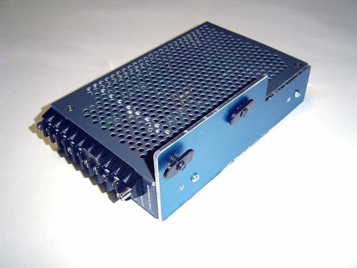
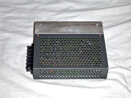
Power Supply Lambda LUT-6-5152 provides 5v for servo and digital logic power as well as 15v and -15v for OP Amp and Baratron gauge power. |
|
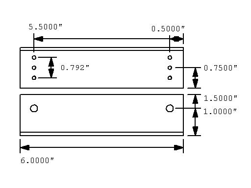
Power Supply Mounting Plate 1/8" thick aluminum panel to attach power supply to 8020 frame. |
|
Power Supply on Mounting Plate Power supply attaches to mounting bracket with 6-32 screws. |
|
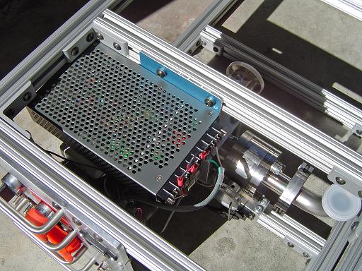
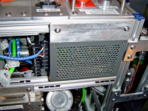
Power Supply Attached to Frame Power supply mounts on frame. |
|
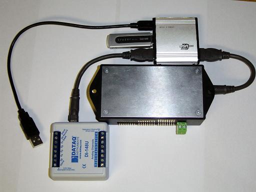
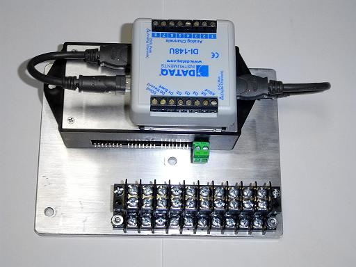
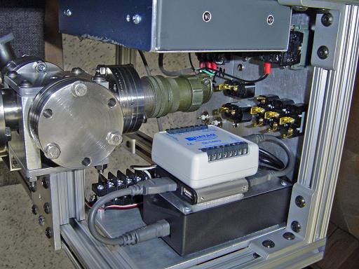
Control System USB control system includes 512MB of memory, a USB 2.0 hub, an 8 channel analog data logger, and an 8 channel servo controller. The Data logger is a DATAQ DI-148U, providing 8 analog inputs and 6 digital inputs at 14400 samples per sec. The servo controller is an ACS-USB-SERVOII and provides 8 servo outputs, 8 digital outputs, and 8 digital inputs. |
|
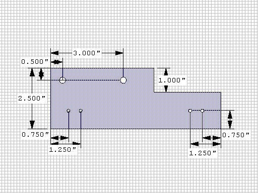
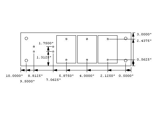
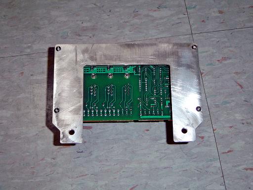
Control System Mounting Plate 1/4" thick aluminum plate holds control system behind control panel. The locations of the holes to mount the barrier strips are 0.375", 0.685", and 0.995" from the left side of the plate. |
|
Control System on Mounting Plate Control system components mount vertically on top of each other, held together by 3M dual lock. Systems connect to the USB hub with 6" USB cables. (This mounting plate was subsequently removed due to space and access issues) |
|
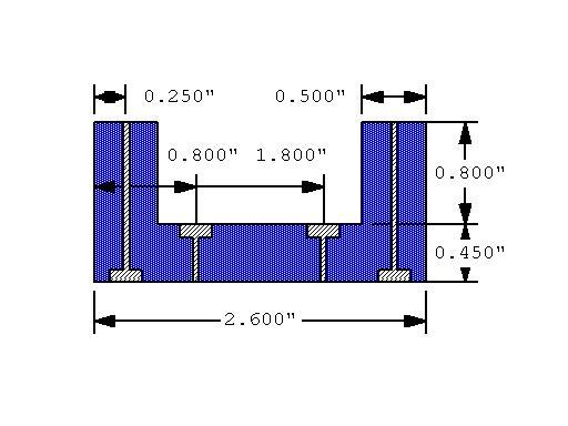
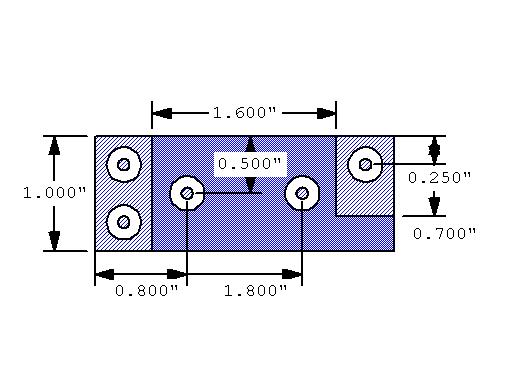
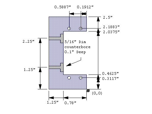
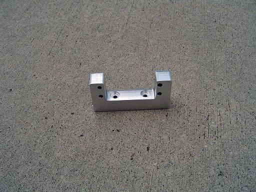
Servo Mounting Block Side view Drilled holes for 6-32 screws are 5/32" in diameter and have a 5/16" counter bore to 0.1" in depth. |
|
Servo Mounting Block Top view 0.3" cut off of one of the side supports to allow servo control wires to exit. |
|
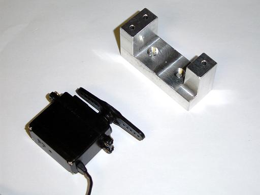
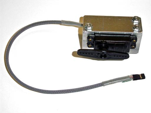
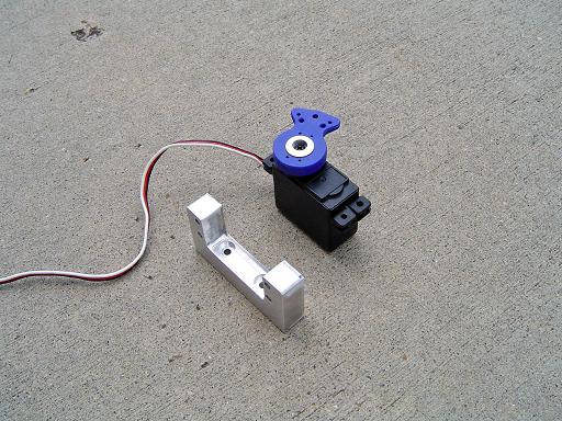
Servo Mounting Block Servo for controlling vacuum throttling valve. |
|
Servo Mounting Block (3/6/2006) Expandable cable loom added to protect servo cable. |
|
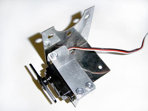
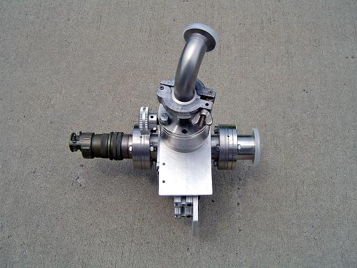
Servo Mounted on 2.75" CF Bracket Servo is attached to a 2.75" CF adaptor bracket for mounting on the valve body. |
|
Mounted Servo Servo bracket mounts on throttling valve. |
|
Servo Valve Control Servo links to valve with 1/16" titanium rod. |
|
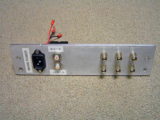
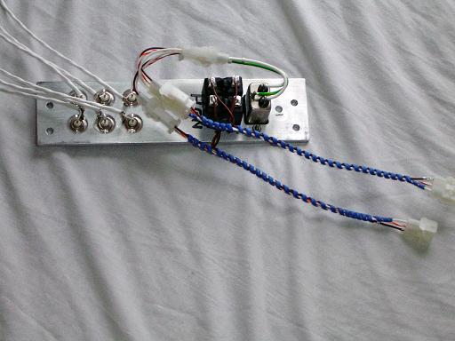
Power Input Panel Power input panel provides AC power to reactor control systems as well as 6 BNC outputs. Each BNC connector hole is 3/8" in diameter and has a 0.75" counter bore to 0.1" depth on the back. |
|
Power Input Panel Power input panel contains an AC power input filter and 6 BNC connectors for general purpose I/O. |
|
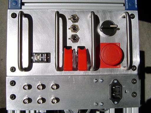
Front Panels Front panel mounted on reactor. |
|
Control System Mounted Control system mounts on frame. |
|
Web cam Mounting Flange (6/10/2006) Milled out of 1/8" aluminum, attached web cam mount to 2.75 CF flange view port. |
|
Web cam Mounting Spacer (6/10/2006) Milled out of 1/2" HDPE |
|
Web cam Mounting Flange (6/10/2006)
|
|
Web cam Mount Cover (6/10/2006)
|
|
Web cam Mount Interior (6/10/2006)
|
|
Servo Controller Retrofit (7/3/2006) ACS-USB-SERVOII is being replaced with a Parallax USB servo controller. |
|
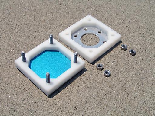
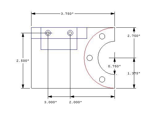
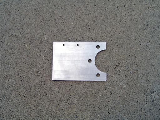
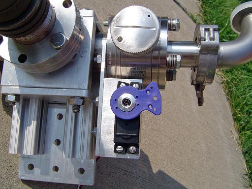
Conflat Mounting Plate (7/17/2006) This is a retrofit for the valve control servo since the stainless steel plate flexed too much during operation. |
|
Conflat Mounting Plate (7/17/2006) Milled out of 1/8" aluminum. |
|
Conflat Mounting Plate (7/17/2006) Mounted on vacuum hub. |
|
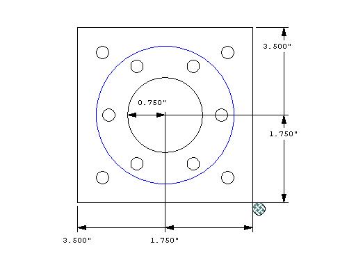
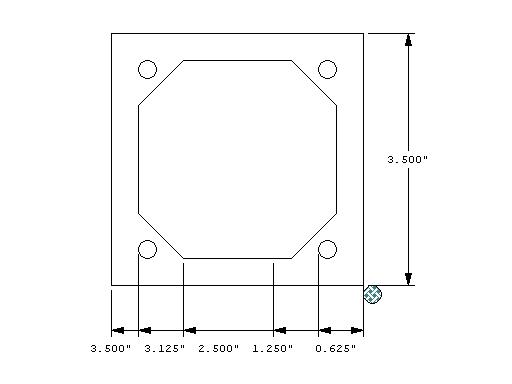
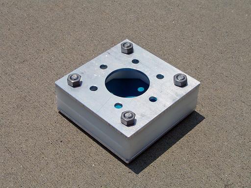
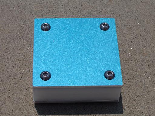
Servo Mount (7/17/2006) Servo mount retrofit, milled out of 1/2" aluminum. |
|
Servo Mount (7/17/2006)
|
|
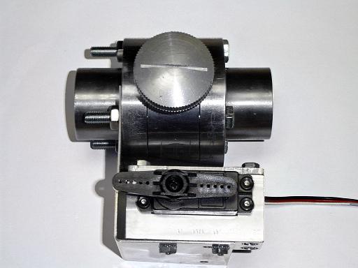
Servo Mount (7/17/2006) Servo mount with tower pro servo (futaba equivalent) outfitted with servo saver. |
|
Servo Mount (7/17/2006) Servo mounted on vacuum hub with 6-32 screws. |
|
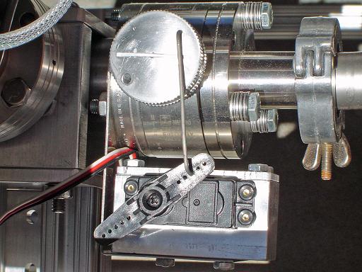
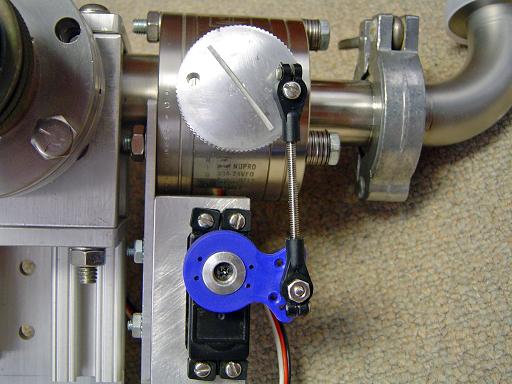
Servo Linkage (11/05/2006) Linkage connects servo to throttle valve. |
|
Control Panel (11/05/2006) Switches replaced and wired with teflon wire. |
|
Control Panel (11/05/2006)
|
|
Power Input Panel (11/05/2006) Thermal breakers added. |
|
Power Input Panel (11/05/2006)
|
|
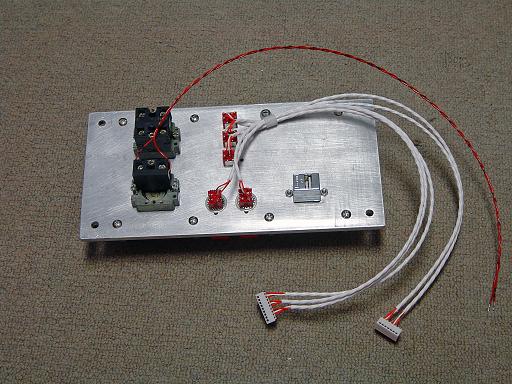
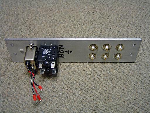
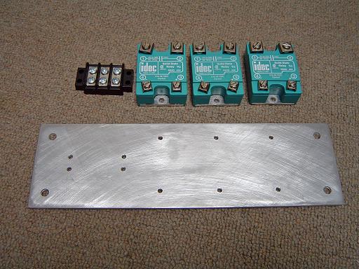
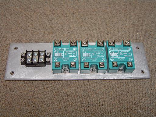
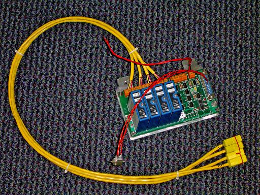
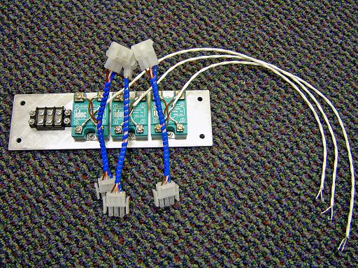
Relay Panel (3/16/2007) |
|
Relay Panel (3/16/2007) Three 40A 120V solid state relays mount on reactor frame to control internal switching of 120v power to pumps and cooling systems. |
|
Relay Panel (3/16/2007) Relays and barrier strip mount on plate |
|
Thermocouple monitor mount (10/13/2007) Attaches thermocouple monitor to reactor frame. |
|
Thermocouple monitor mount (10/13/2007)
|
|
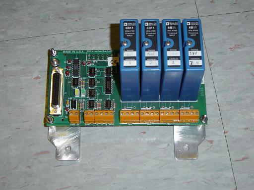
Thermocouple monitor (10/13/2007) Attached to mounting panel. System can monitor 4 thermocouple channels with 1500V isolation on each channel. |
|
Thermocouple monitor (12/3/2007) Thermocouple cable connects to monitor for use on type K thermocouples |
|
Relay panel connectors (1/05/2008) Molex connectors are attached to the relay panel. |
|
Power input panel connectors (1/05/2008) Molex connectors are attached to the power input panel. |
|
Control panel connectors (1/05/2008) Molex connectors are attached to the control panel. |
|
12V power supply mount (1/20/2008) Mounts 12V power supply to reactor frame. Machined from 1.5"x1.5"x1/8" aluminum L channel. |
|
12V power supply (1/20/2008) Lambda LUS-10A-12 power supply provides 12V at 4.2A to power ECRF preamplifiers and instrumentation. |
|
12V power supply (1/20/2008) Mounts to reactor frame. |
|
Thermocouple monitor mounted (1/20/2008) Mounts to reactor frame. |
|
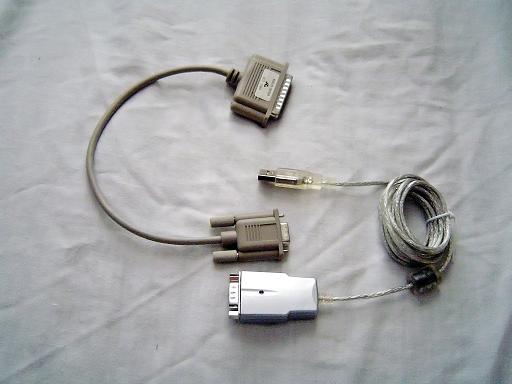
Thermocouple monitor interface (1/20/2008) FTDI chipset based usb to serial converter connects thermocouple monitor to control system. |
|
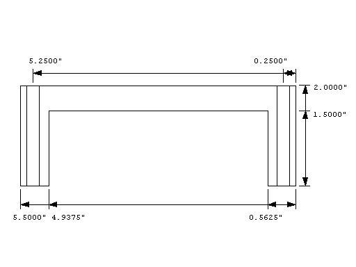
Convectron mount (2/15/2008) Mount for convectron vacuum gauge, wide version. |
|
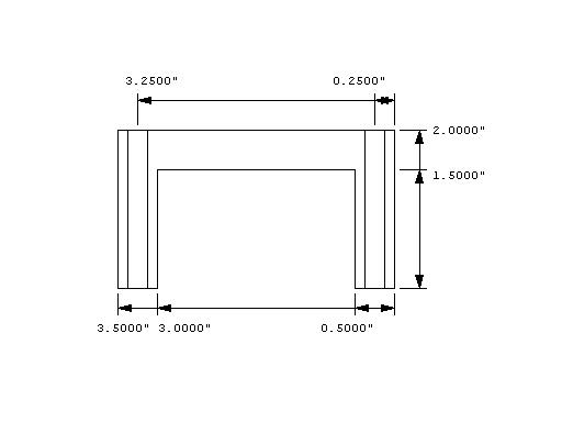
Convectron mount (2/15/2008) Mount for convectron vacuum gauge, narrow version. |
|
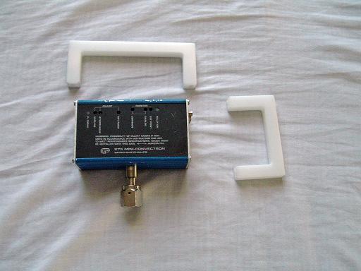
Convectron mounts (2/15/2008) Wide and narrow versions. |
|
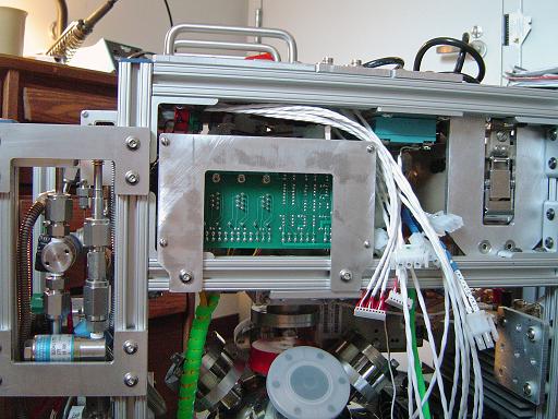
Convectron mounts (5/6/2008) Control system test setup used for data acquisition. |
|
|
|
|
|
|
|
|
|
|
|
|
|
|
|
|
| Useful links: http://www.fusor.net/ Open Source Fusion Research Consortium. |
|
By attempting to reproduce any experiments or devices listed on this domain in part or in whole, you agree to hold me harmless against any lawsuit or liability. Copyright © 1998 - 2005 by Andrew Seltzman. All rights reserved. |
|
| Contact me at: admin@rtftechnologies.org | |