| Turbocharger Gas Turbine |
 |
 |
 |
 |
 |
 |
 |
| A small gas turbine constructed from a t3/t4 turbocharger. |
|
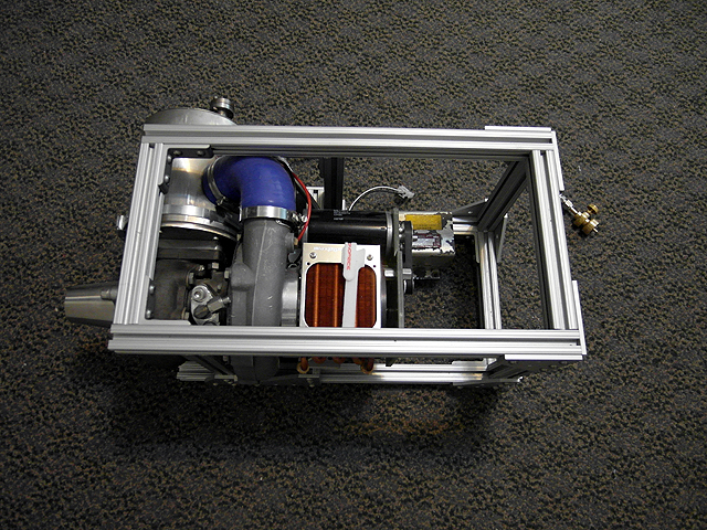 |
Gas turbine (6/30/2013) Mounted on frame.
|
Gas turbine test (6/30/2013) Test with liquid propane.
|
|
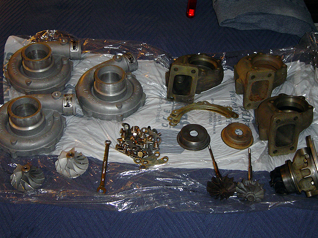 |
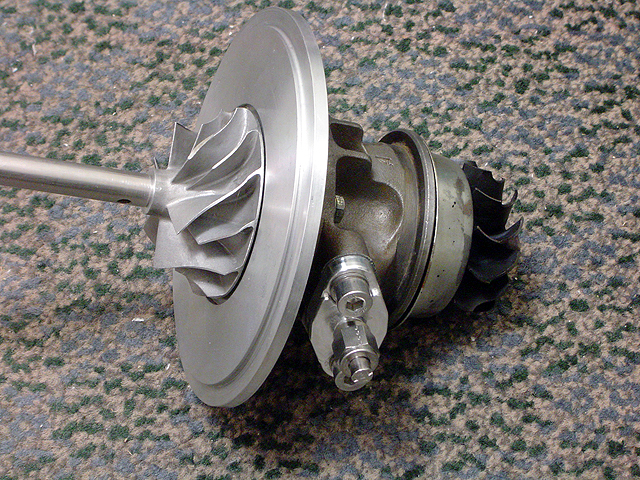
Turbocharger parts (6/30/2013) Parts from t3/t4 turbochargers, best ones were selected for the gas turbine.
|
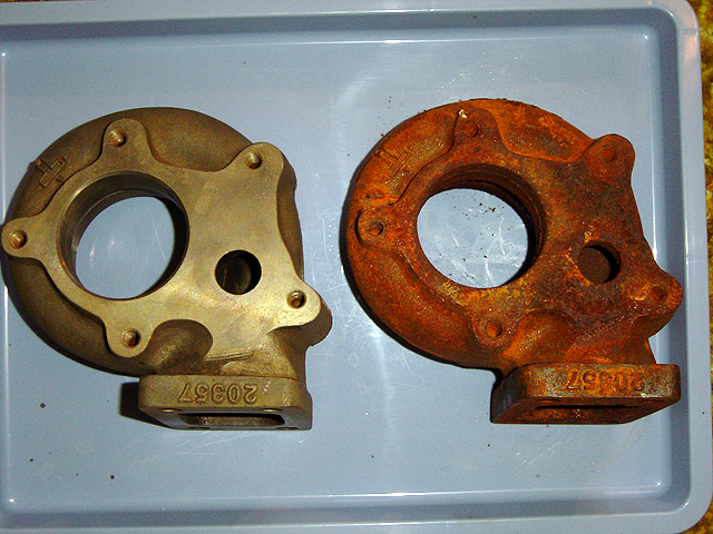 |
Turbocharger parts (6/30/2013) Turbine casings were cleaned by placing on an aluminum plate and submersing in dilute hydrochloric acid. The aluminum is oxidized while the rust on the iron turbine casing is reduced.
|
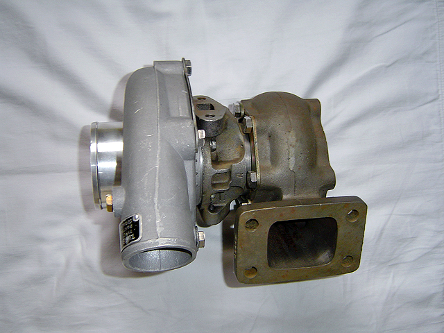 |
Turbocharger (6/30/2013) Cleaned and assembled turbocharger. |
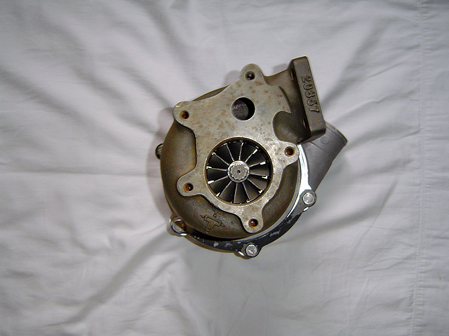 |
Turbocharger (6/30/2013) Cleaned and assembled turbocharger.
|
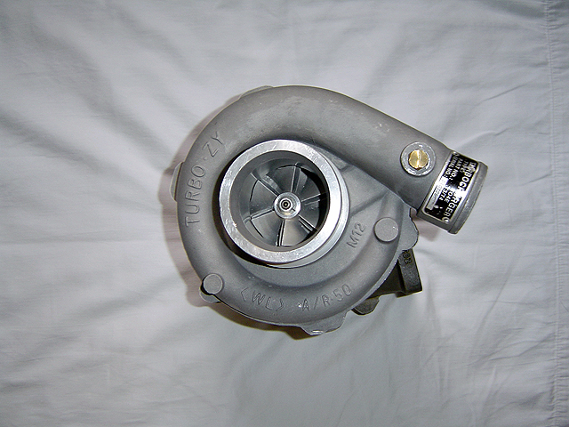 |
Turbocharger (6/30/2013) Cleaned and assembled turbocharger. |
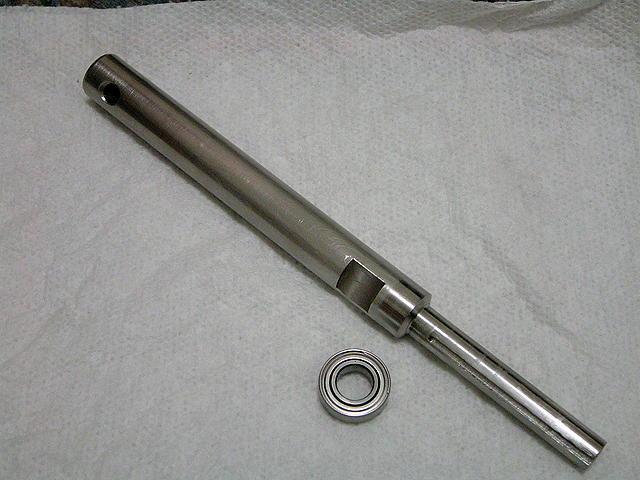 |
Starter/generator shaft (6/30/2013) Shaft screws onto compressor end of turbine and allows a motor to spin up the turbine through a gearbox and act as a generator during operation.
|
 |
Starter/generator shaft (6/30/2013) Shaft screwed onto compressor.
|
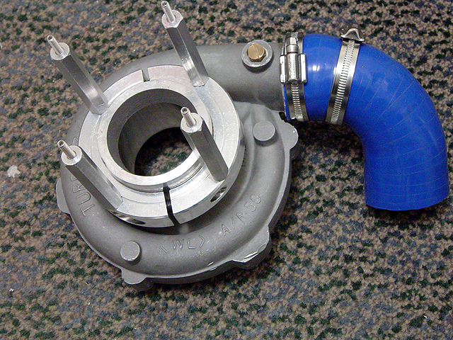 |
Diffuser (6/30/2013) Compressor diffuser with rubber hose and gearbox standoffs. |
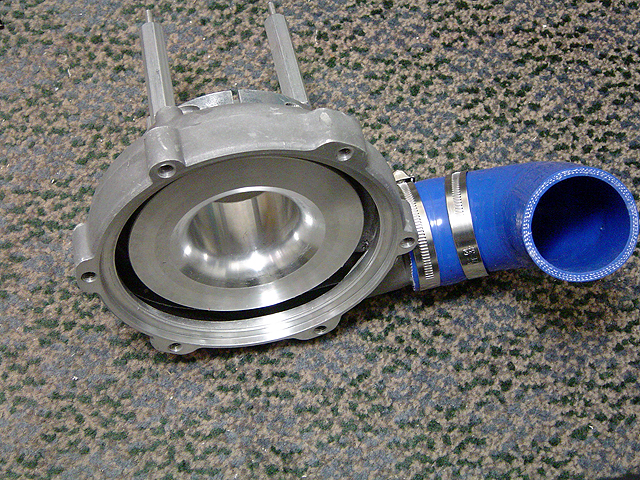 |
Diffuser (6/30/2013) Compressor diffuser with rubber hose and gearbox standoffs.
|
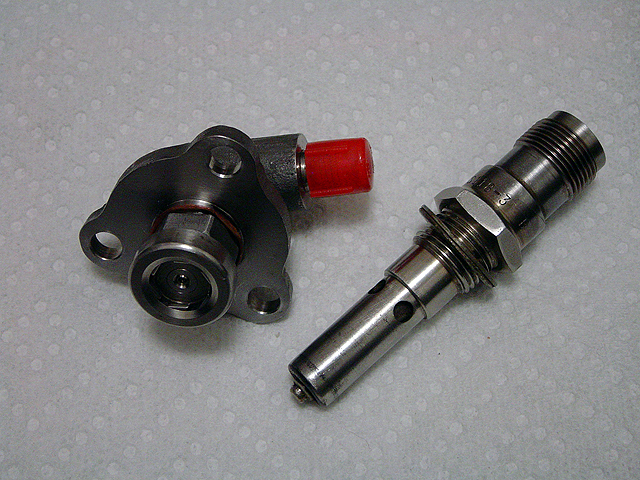 |
Fuel/ignitor (6/30/2013) Fuel nozzle and ignitor plug.
|
 |
Ignitor (6/30/2013) Ignitor plug.
|
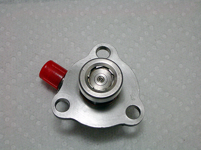 |
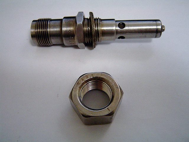
Fuel Nozzle(6/30/2013) Fuel spray nozzle. Dual cone nozzle for better atomization at higher flow rates. Swirl vanes for better mixing with air
|
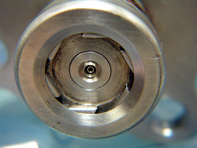 |
Fuel Nozzle(6/30/2013) Fuel spray nozzle. Dual cone nozzle for better atomization at higher flow rates. Swirl vanes for better mixing with air
|
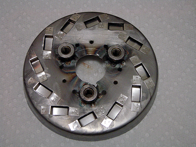 |
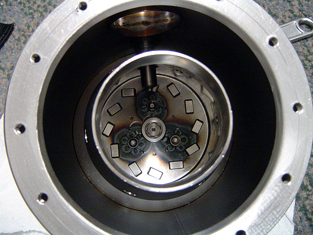
Combustion liner cap (6/30/2013) Combustor cap with counter swirl vanes for good air/fuel mixing.
|
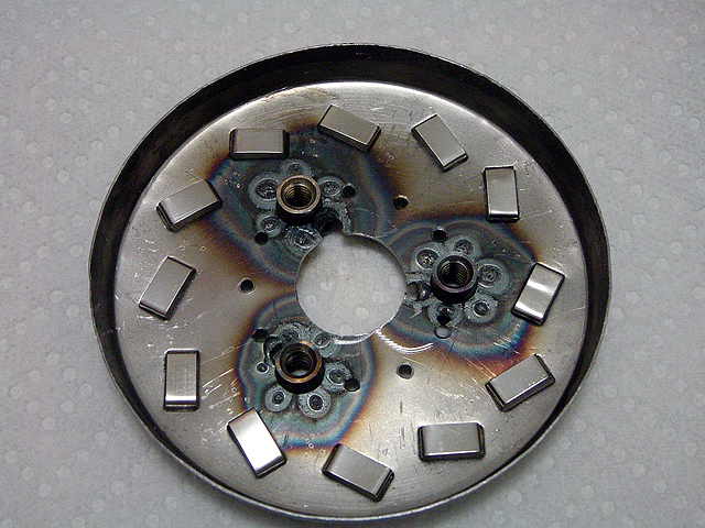 |
Combustion liner cap (6/30/2013) Combustor cap with counter swirl vanes for good air/fuel mixing.
|
 |
Combustion liner cap (6/30/2013) Combustor cap with counter swirl vanes for good air/fuel mixing.
|
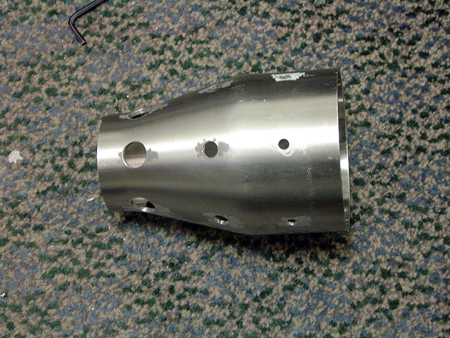 |
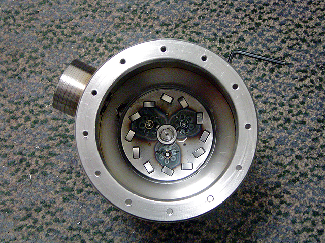
Combustion liner (6/30/2013) Combustor liner with air dilution holes.
|
 |
Combustion liner (6/30/2013) Combustor liner with air dilution holes.
|
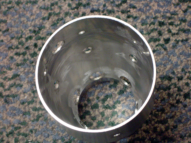 |
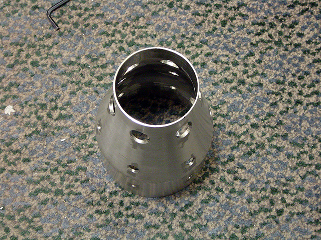
Combustion liner (6/30/2013) Combustor liner with air dilution holes.
|
 |
Combustion liner (6/30/2013) Combustor liner with air dilution holes. Also shown is ignitor plug feed through hole
|
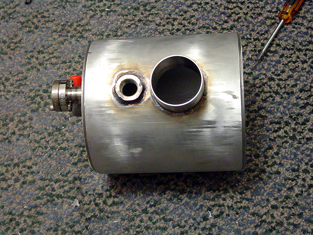 |
Combustor (6/30/2013) Combustor casing with ports for air and ignitor plug.
|
 |
Combustor (6/30/2013) Combustor casing with fuel nozzle port. |
 |
Combustor (6/30/2013) Combustor with fuel nozzle and end cap.
|
 |
Combustor (6/30/2013) Combustor with fuel nozzle, end cap and combustion liner.
|
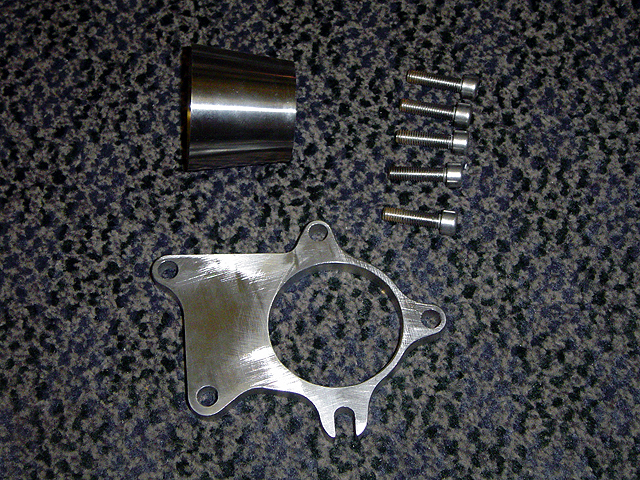 |
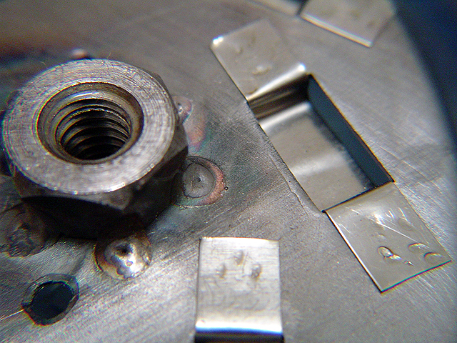
Nozzle (6/30/2013) Nozzle and end plate.
|
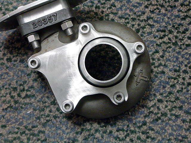 |
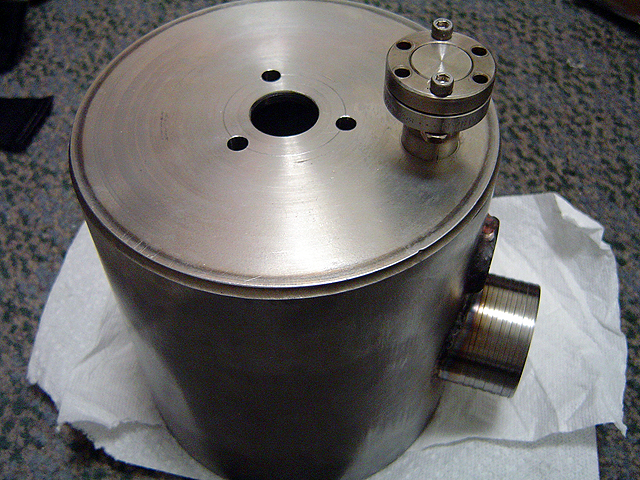
Turbine casing (6/30/2013) With nozzle and end plate.
|
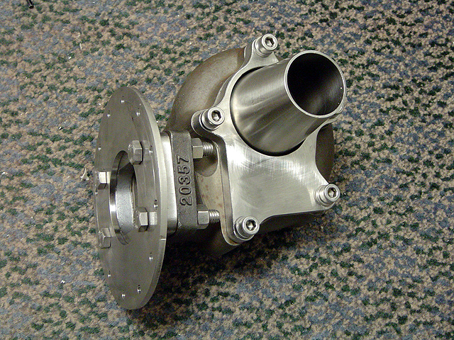 |
Turbine casing (6/30/2013) With nozzle and end plate.
|
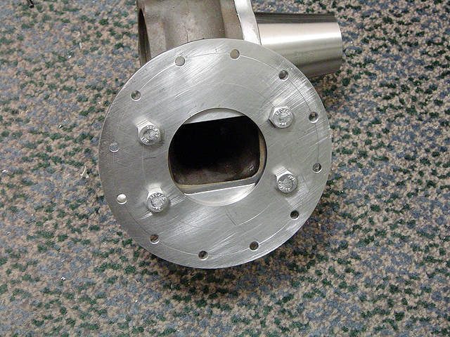 |
Turbine casing (6/30/2013) With nozzle and end plate.
|
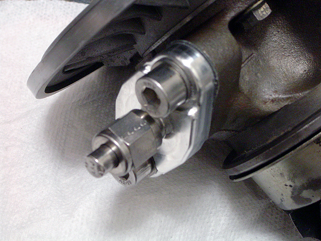 |
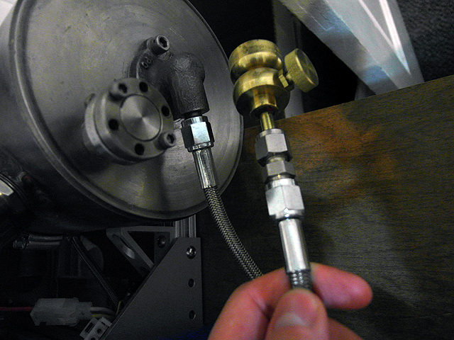
Oil feed (6/30/2013)
|
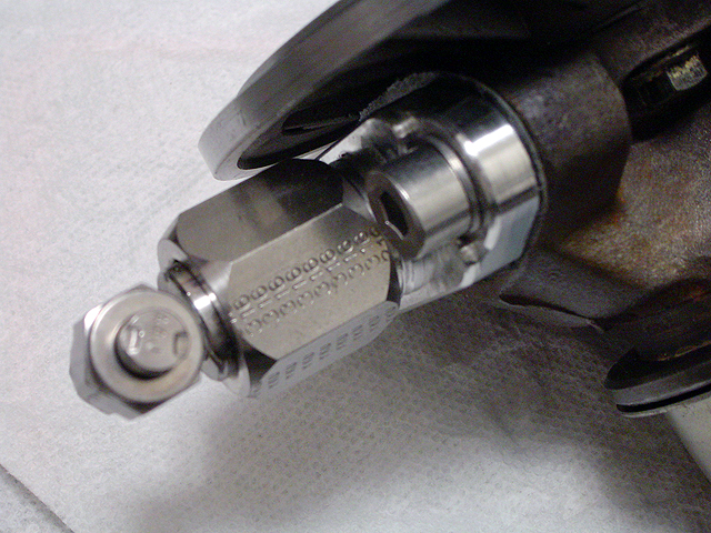 |
Oil return (6/30/2013)
|
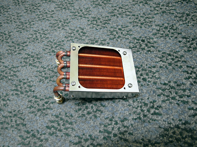 |
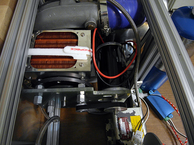
Radiator (6/30/2013) Cools returning oil
|
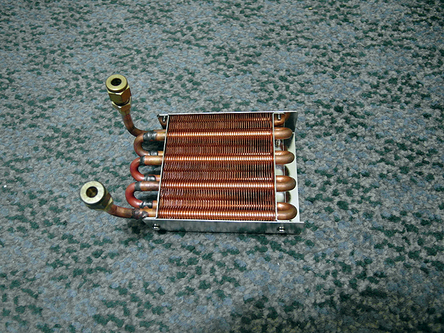 |
Radiator (6/30/2013) Cools returning oil
|
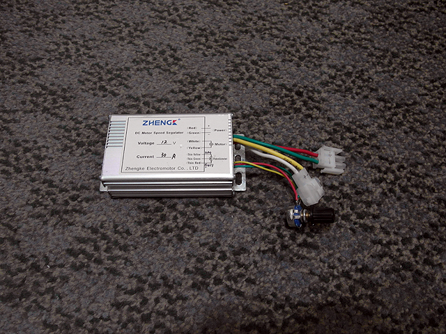 |
Motor controller (6/30/2013) PWM speed controller.
|
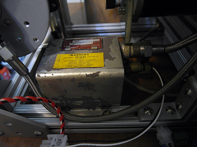 |
Ignition exciter (6/30/2013) Ignition exciter.
|
 |
Oil System (6/30/2013) IDEX micro pump and oil reservoir.
|
 |
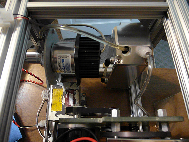
Gearbox (6/30/2013) Gearbox and starter motor.
|
 |
Fuel System (6/30/2013) Modified propane torch head.
|
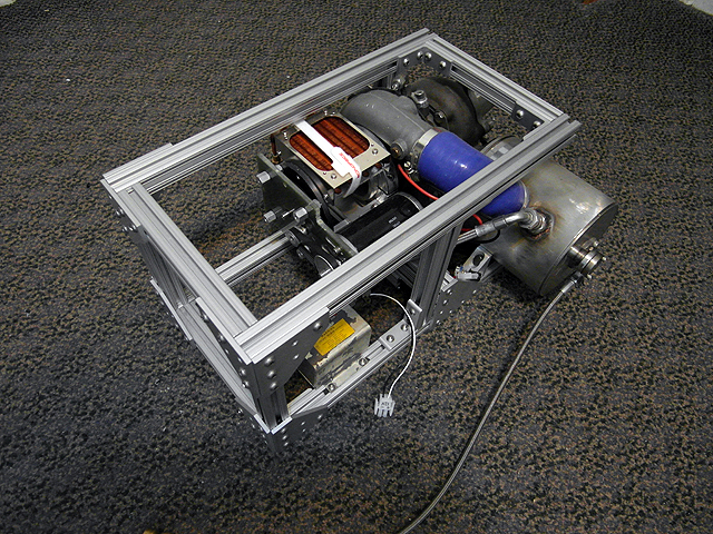 |
Gas turbine frame (6/30/2013) 8020 mounting frame
|
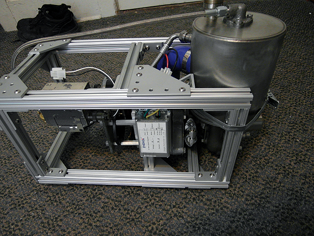 |
Gas turbine frame (6/30/2013) 8020 mounting frame
|
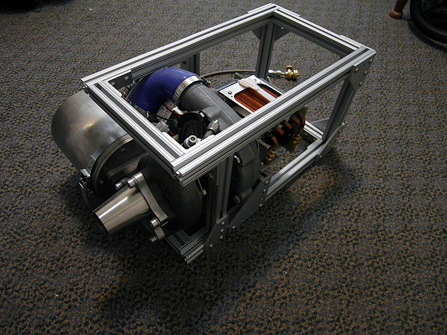 |
Gas turbine frame (6/30/2013) 8020 mounting frame
|
|
Gas turbine frame (6/30/2013) 8020 mounting frame
|
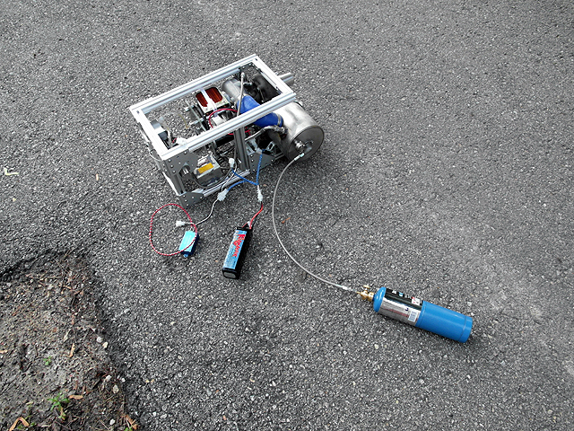 |
Gas turbine test (6/30/2013) Test with liquid propane
|
By attempting to reproduce any experiments or devices listed on this domain in part or in whole, you agree to hold me harmless against any lawsuit or liability. Copyright © 1998 - 2013 by Andrew Seltzman. All rights reserved. |
|
| Contact me at: admin@rtftechnologies.org | |