| 5 Axis Desktop CNC Spindle |
 |
 |
 |
 |
 |
 |
 |
| High speed spindle. 1/8" shank mill bit or PCB tooling bit directly held in high speed bearings. Maximum speed of 80kRPM.
|
|
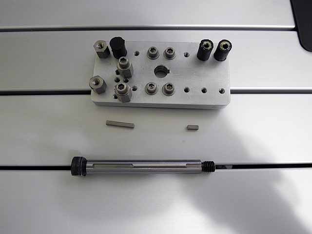 |
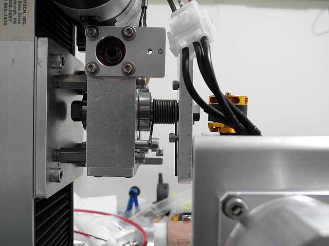
High speed spindle base (6/18/2011) High speed spindle base plate ang keyed shaft. |
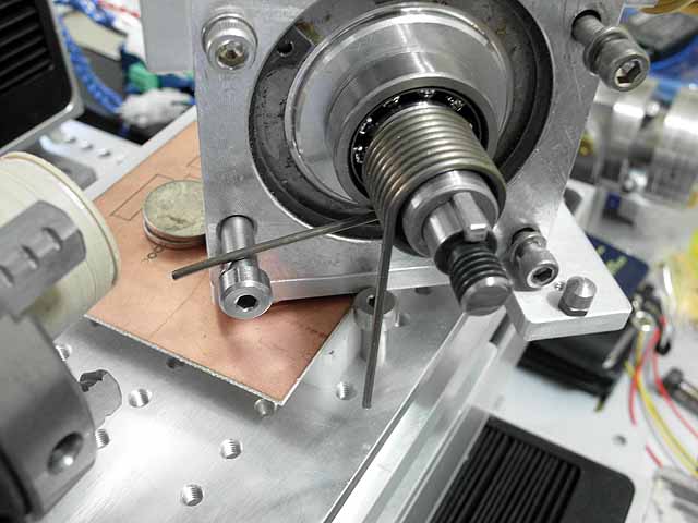 |
B-axis mount (6/18/2011) Angular contact bearings on front and back of worm gear stage stiffen shaft. Anti-backlash spring provides constant tension between the gear and the worm, preventing any play or vibration. The torque produced by the spring will exceed the breaking strength of the mill bit (eg: the bit tip will break before the b-axis tracks improperly).
|
 |
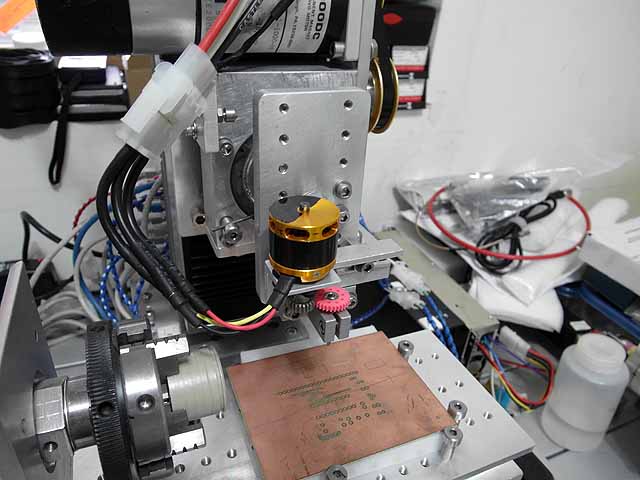
Spindle mounted (6/18/2011) Angular contact bearings on front and back of worm gear stage stiffen shaft. Anti-backlash spring provides constant tension between the gear and the worm, preventing any ply or vibration. The torque produced by the spring will exceed the breaking strength of the mill bit (eg: the bit tip will break before the b-axis tracks improperly).
|
 |
Mill bit holder (6/18/2011) Rod holder is adapted to hold 1/4" OD 1/8" ID flanged high speed ceramic bearings. |
 |
Anti-backlash spring (6/18/2011) Anti-backlash spring side view, at tension.
|
 |
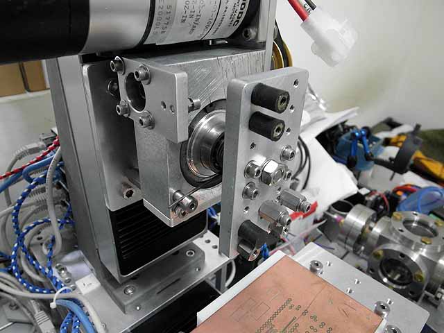
High speed spindle (6/18/2011) Completed high speed spindle.
|
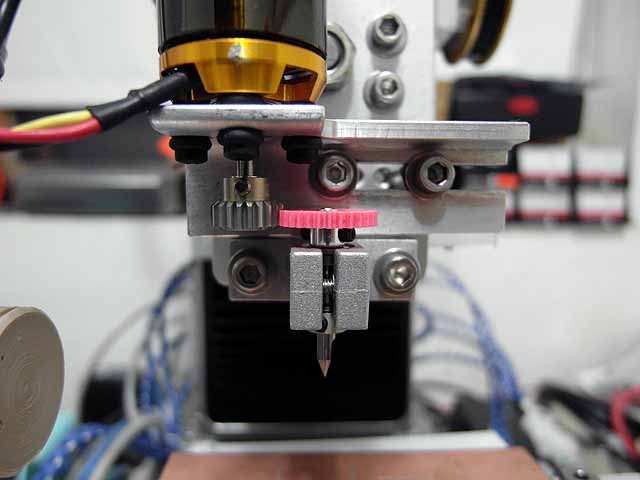 |
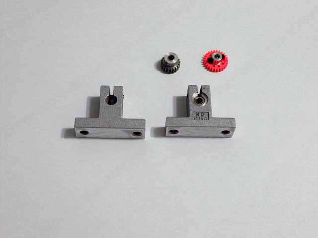
High speed spindle (6/18/2011) Completed high speed spindle. High speed slot car gears are used to drive the mill bit. Note that the gears hive duel opposed set screws to maintain balance. The bit is held directly in the bearings, and the drive gear is attached directly to the bit. The low rotating mass greatly reduces vibrations. The plastic gear reduces noise.
|
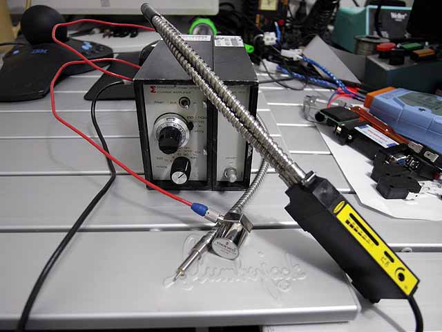 |
Spindle balancing setup (6/18/2011) Endevco 2217E piezoelectric accelerometer, charge amplifier, and Banner D12SP6FVQ fiber optic sensor.
|
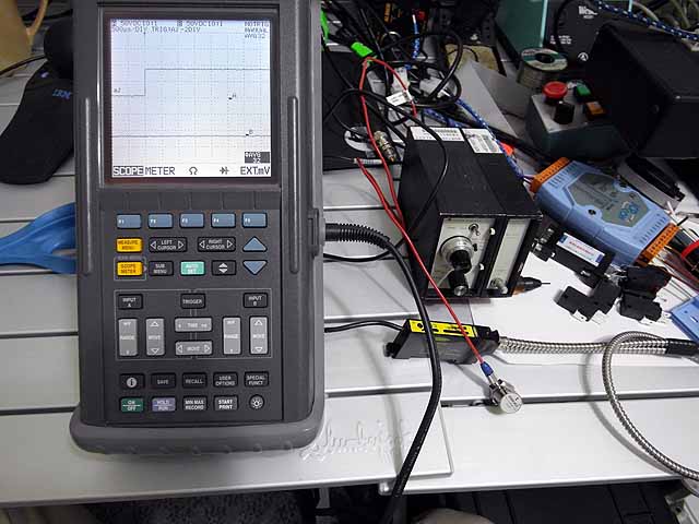 |
Spindle balancing setup (6/18/2011) With oscilloscope.
|
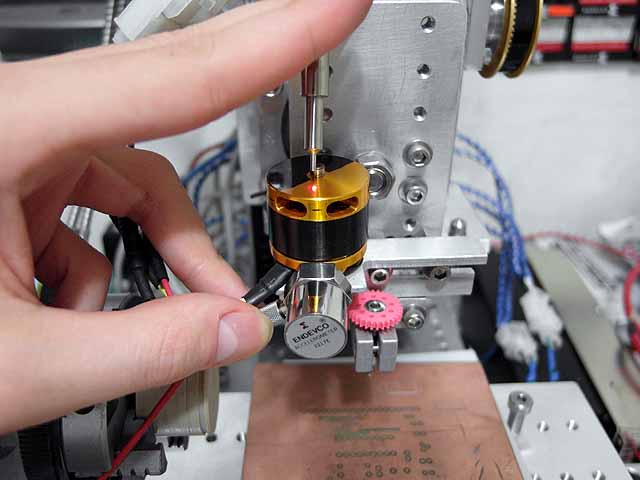 |
Spindle balancing (6/18/2011) Fiber optic sensor is used to determine position of rotor while accelerometer determines position of rotor imbalance.
|
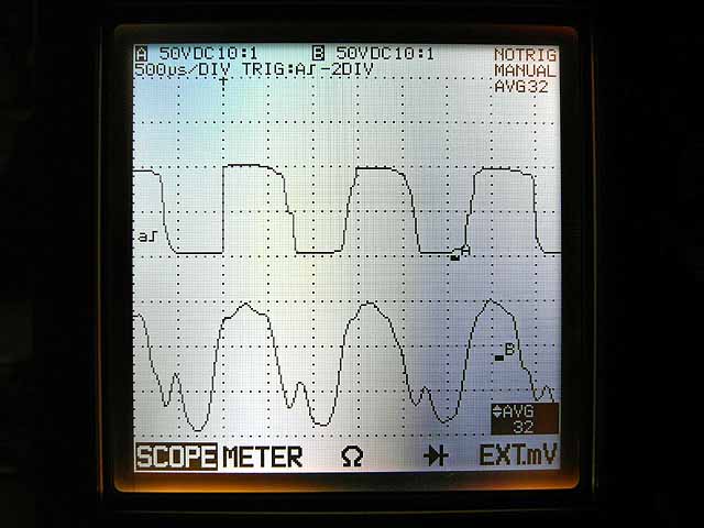 |
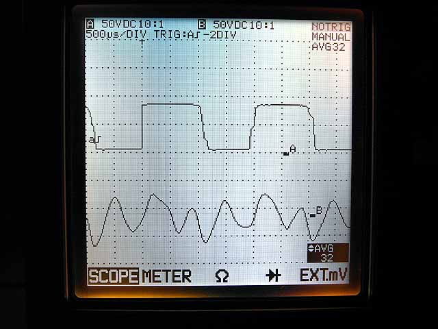
Spindle balancing (6/18/2011) Top trace: Fiber optic sensor output Bottom trace: Spindle motor vibration
|
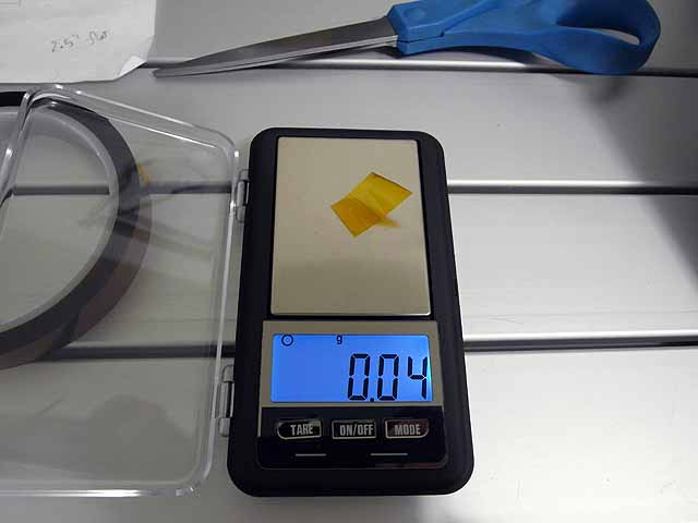 |
Spindle balancing (6/18/2011) 40mg of kapton tape is added to the light side of the motor.
|
 |
Spindle balancing (6/18/2011) Reduces vibration after balancing, note that motor was fairly well balance before addition of kapton tape, however, the vibration and noise is now significantly reduced. Top trace: Fiber optic sensor output Bottom trace: Spindle motor vibration
|
|
|
|
|
By attempting to reproduce any experiments or devices listed on this domain in part or in whole, you agree to hold me harmless against any lawsuit or liability. Copyright © 1998 - 2013 by Andrew Seltzman. All rights reserved. |
|
| Contact me at: admin@rtftechnologies.org | |