| Geiger Counter |
 |
 |
 |
 |
 |
 |
 |
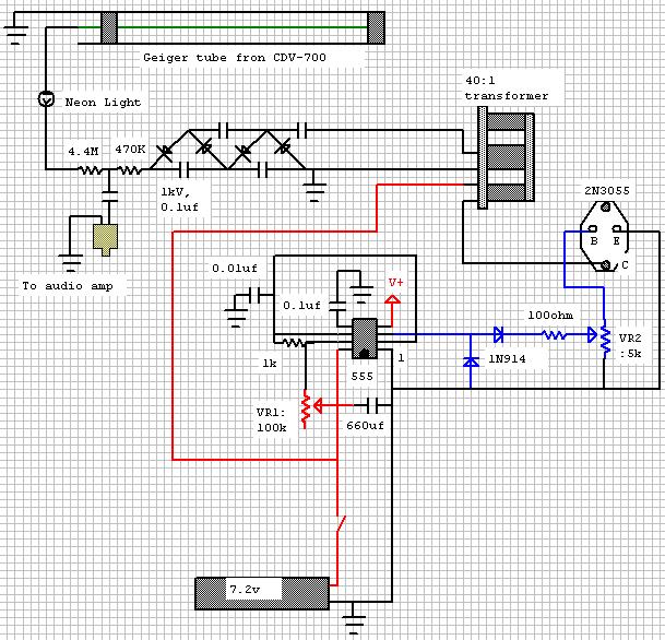
| Overview: A simple geiger counter constructible for about $25. Power is supplied from a 7.2v Ni-Cad pack (used in remote control cars). The geiger tube was salved from a broken CDV-700 geiger counter ($10 on e-bay). The use of a 555 timer IC to control the switching allows the use of the step up transformers that will not work with a feedback coil to automatically tune the system to resonance. |
|
Operation: The 555 timer switches the 2N3055 transistor, supplying 7.2v at about 10kHz to the primary coil of the step up transformer (found in computer monitors, not the flyback though). The secondary of the transformer outputs 225v into a voltage multiplier, supplying the required 900v to the geiger tube. When ionizing radiation enters the geiger tube, it ionizes the internal gas, allowing an electrical discharge through the tube. The discharge causes the neon light in series with the tube to blink, as well as causing a voltage spike from the capacitor in parallel with the tube. This spike is heard as a "click" on an external audio amp (computer speakers). |
|
Construction and tuning: It is recommended to built this circuit on a one-pad-per-hole prototyping board. The voltage multiplier should be far away from the timer to avoid damaging it if high voltage arcs occur between the solder pads. In addition it is helpful to cut a row of pads off the board to separate the voltage multiplier and the timer. After constructing it is necessary to tune the circuit to the proper voltage and frequency. A multi meter with a 1000v rating is required since the voltage multiplier should output about 900v. Center both potentiometers (vr1 and vr2). VR1 controls frequency and VR2 controls voltage output. Turn circuit on and adjust VR1 until the voltage on the output of the multiplier is at the maximum (This should not occur on either end of the potentiometer, but somewhere in the middle). The peak voltage represents the frequency that the transformer's efficiency is at it's maximum. The voltage ( DC ) should be measured between ground and the output of the multiplier. Next connect the geiger tube and increase the voltage by adjusting VR2 until you can hear occasional clicks on the speakers. The switching of the transistor will also be heard in the speakers as a high frequency tone and should not be confused with the clicks.
|
|
| Geiger counter audio:
|
|
 |
|
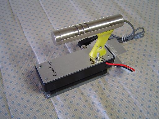 |
Geiger counter: Neon light in series with geiger tube blinks when counts are detected. Locking power switch connects 7.2v battery and allows for selection if internal or external audio. |
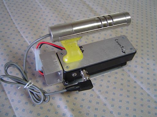 |
Geiger counter: Probe is connected via a bnc connector. An external audio amplifier can be connected via a headphone connector. |
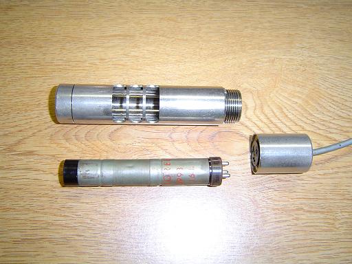 |
Geiger tube: Geiger tube is a Victoreen 6993 from a CDV-700 geiger counter. |
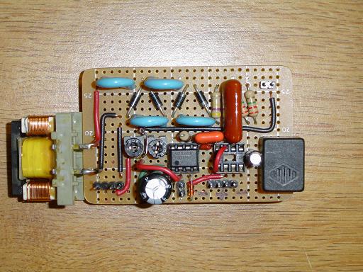 |
Geiger circuit: Step up transformer is switched by 555 timer and provides input to voltage multiplier. |
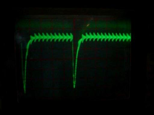 |
Geiger detection capture: Oscilloscope capture of pulses resulting from two particle detection events. The smaller pulses are the RLC oscillations driving the multiplier stack. |
By attempting to reproduce any experiments or devices listed on this domain in part or in whole, you agree to hold me harmless against any lawsuit or liability. Copyright © 1998 - 2005 by Andrew Seltzman. All rights reserved. |
|
| Contact me at: admin@rtftechnologies.org | |