| Basic Stamp 2 Control System |
 |
 |
 |
 |
 |
 |
 |
| Overview: The Basic Stamp is a micro controller designed for robotics applications. However for use in most modular and large scale robots, the basic stamp requires physical and electrical protection, as well ar a power source and programming port (serial, RS-232). This system includes a 900 MHz radio link (>1000ft range) as well as an 8 channel PWM output and joystick input. |
|||||||||||||||||||||||||||||||||||||||||||||||||||||||||||||||||||||||||||||||||
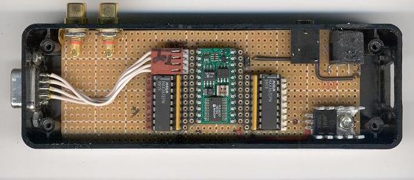
Processor Module: The Basic Stamp 2, by Parallax-inc, is enclosed in a radio-shack project box and assembled on a radio shack circuit board. The bs2 is mounted in an IC socket for easy removal or upgrade. My present design will work with the BS2, BS2SX, PS2E, and BS2P24. It used MAX367EPN over-voltage / surge suppressor chips, available as free samples from Maxim IC, to protect the bs2-ic from voltages outside the TTL/CMOS range. The MAX367s are run at 5v, restricting the voltage into the inputs to 5.25v to -0.25v and can handle inputs of +- 40v. I/O live 0 is dedicated to an input button. I/O lines 1-3 (external audio connectors) are over-current protected by a series 1K-ohm resistor. I/O lines 4-15 can be connected to via an external DB-15HD connector, available at radio-shack. Between the bs2 and the MAX367s are test points, similar to a breadboard, as well as sockets for pull-up and pull-down resistor packages. Power is regulated via a 7805 5v regulator, that is connected to the BS2's 5v live and the MAX367 V+ lines. |
|||||||||||||||||||||||||||||||||||||||||||||||||||||||||||||||||||||||||||||||||
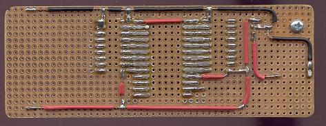 |
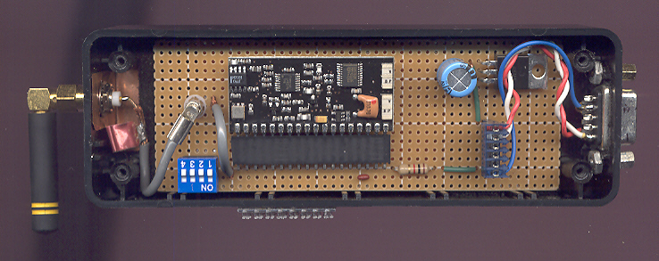
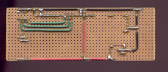
These are pictures of the Processor assembly during construction. The 9 pin sockets next to the stamp are for pull-up or pull-down resistor blocks. The 24 pin sockets can be used as test points or for jumper wires. The pin headers go to the DB-15 connector(not shown). | ||||||||||||||||||||||||||||||||||||||||||||||||||||||||||||||||||||||||||||||||
 |
|||||||||||||||||||||||||||||||||||||||||||||||||||||||||||||||||||||||||||||||||
 |
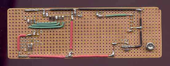
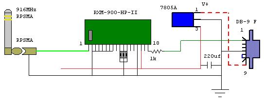
Electrical Diagram: The MAX367s connect to gray rectangles denoting the pin headers. These connect to the DB-15f connector on the processor module. Different colored lines that cross do not connect. |
||||||||||||||||||||||||||||||||||||||||||||||||||||||||||||||||||||||||||||||||
|
|||||||||||||||||||||||||||||||||||||||||||||||||||||||||||||||||||||||||||||||||
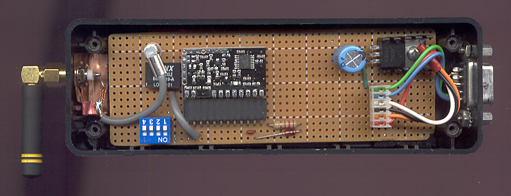
900 MHz Telecommand System: Utilizes the HP-2 series RF modules (pin compatible with the newer HP-3 ) from Linx Technologies . Although encased in plastic enclosures, each module has a copper foil ground plane at the bottom of the box which increases the performance of both the RF module and antenna. During operation the antenna is normal to the ground plane (horizontal during scan). Multiple channels from 902-928MHz are selectable via the DIP switch. The modules are capable of transmitting audio or serial data up to 50,000bps, however operation with the basic stamp has only been tested at 9600bps. |
|||||||||||||||||||||||||||||||||||||||||||||||||||||||||||||||||||||||||||||||||
Transmitter: Linx TXM-900-HP-II transmits raw data from the bs2 module at the telecommand station to the receiver on the robot. |
|||||||||||||||||||||||||||||||||||||||||||||||||||||||||||||||||||||||||||||||||
 |
|||||||||||||||||||||||||||||||||||||||||||||||||||||||||||||||||||||||||||||||||
 |
|
||||||||||||||||||||||||||||||||||||||||||||||||||||||||||||||||||||||||||||||||
| Since the module is designed for 0-3v logic levels, a 2.2k series resistor is necessary to operate the module at the 0-5v logic levels generated by the basic stamp. The 5.1v zener diode protects the module from negative and over voltage on the data input. | |||||||||||||||||||||||||||||||||||||||||||||||||||||||||||||||||||||||||||||||||
Receiver: Linx RXM-900-HP-II receives raw data from the transmitter at the telecommand station and outputs it to the bs2 module on the robot. |
|||||||||||||||||||||||||||||||||||||||||||||||||||||||||||||||||||||||||||||||||
 |
|||||||||||||||||||||||||||||||||||||||||||||||||||||||||||||||||||||||||||||||||
 |
|
||||||||||||||||||||||||||||||||||||||||||||||||||||||||||||||||||||||||||||||||
 |
|||||||||||||||||||||||||||||||||||||||||||||||||||||||||||||||||||||||||||||||||
Code: Test code for robot and transmitter Basic Stamp code editor and manual |
|||||||||||||||||||||||||||||||||||||||||||||||||||||||||||||||||||||||||||||||||
By attempting to reproduce any experiments or devices listed on this domain in part or in whole, you agree to hold me harmless against any lawsuit or liability. Copyright © 1998 - 2005 by Andrew Seltzman. All rights reserved. |
|
| Contact me at: admin@rtftechnologies.org | |